
System and Method for Controlling Thrust and/or Tower Loads of a Wind Turbine

a technology for wind turbines and tower loads, applied in passive/reactive control, program control, instruments, etc., can solve problems such as detrimental to the operation and/or structural integrity of wind turbines, and wind turbines are subject to loads

Active Publication Date: 2020-01-23
GENERAL ELECTRIC CO
View PDF5 Cites 7 Cited by
  • Summary
  • Abstract
  • Description
  • Claims
  • Application Information

AI Technical Summary

Benefits of technology

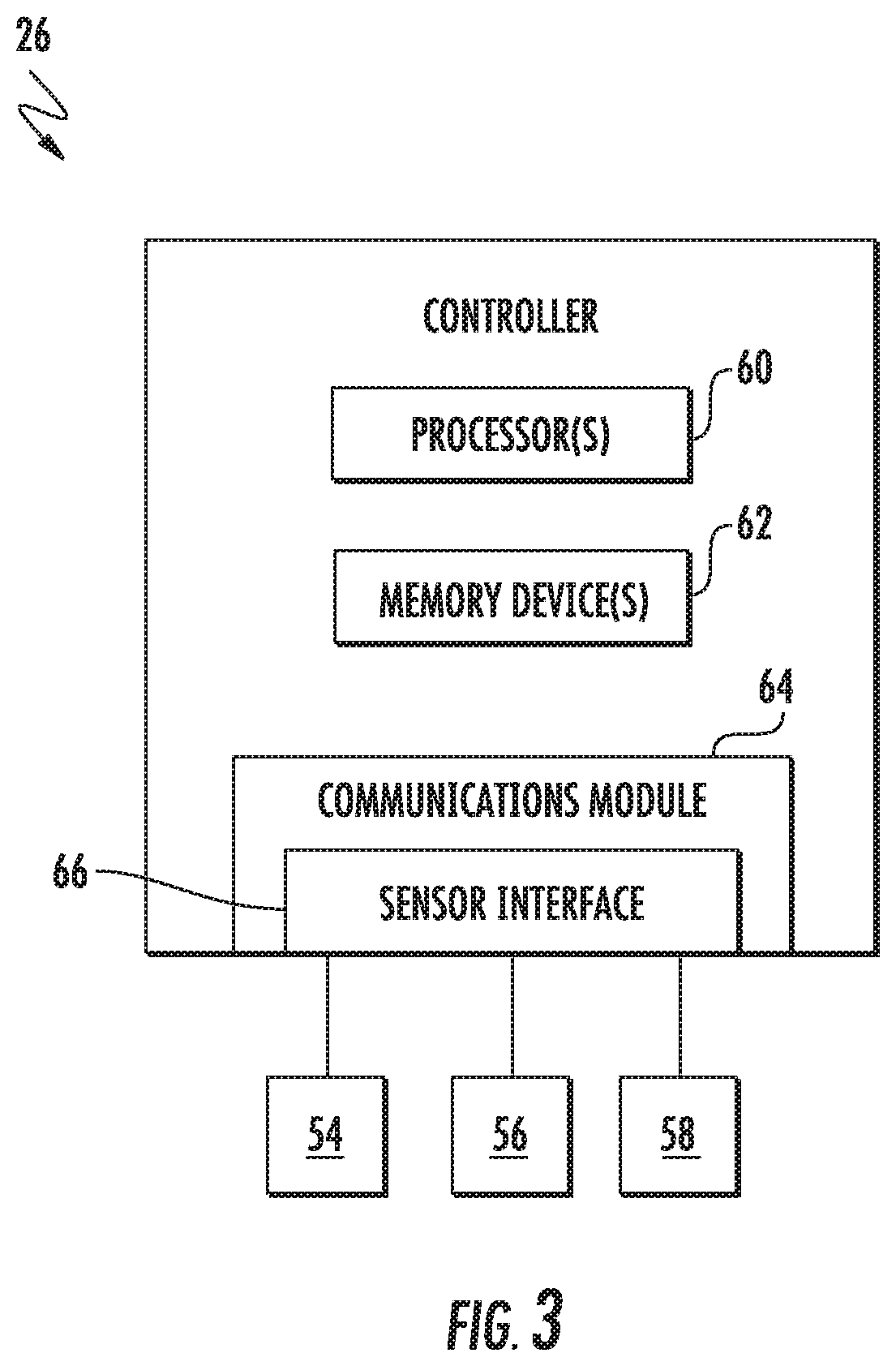
The present disclosure is directed to a method and system for controlling loads on a wind turbine. The method involves using sensors to detect movement of the nacelle or tower of the wind turbine from a reference point, and using the sensor signals to determine the thrust or tower load of the wind turbine. The system includes a controller that receives the sensor signals and generates a deflection profile of the tower along its overall length from the bottom end to the top end. The controller then uses the deflection profile to determine the thrust or tower load of the wind turbine. The technical effect of the invention is to provide a better method for controlling loads on a wind turbine, which can help to increase efficiency and reduce maintenance costs.

Problems solved by technology

Like most dynamic systems, wind turbines are subject to loads that may detrimentally impact the operation and / or structural integrity of the wind turbine.
For conventional wind turbines, it can be a challenge to accurately measure the loads on the tower from aerodynamic thrust and other dynamics occurring in the wind turbine tower over the life of a wind turbine at low cost.

Method used


Image

  • System and Method for Controlling Thrust and/or Tower Loads of a Wind Turbine
  • System and Method for Controlling Thrust and/or Tower Loads of a Wind Turbine
  • System and Method for Controlling Thrust and/or Tower Loads of a Wind Turbine

Examples


Embodiment Construction

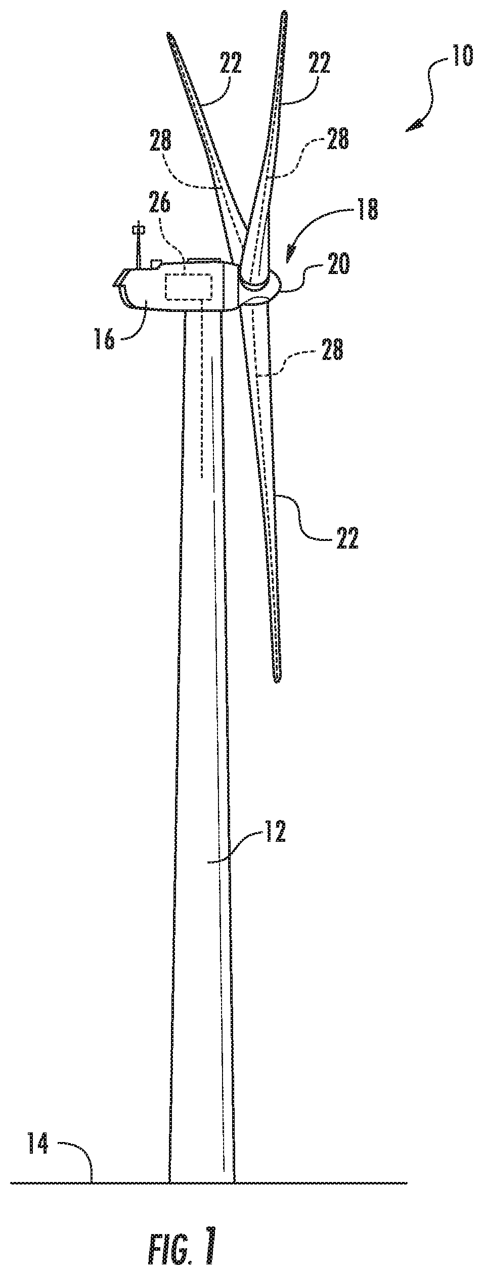
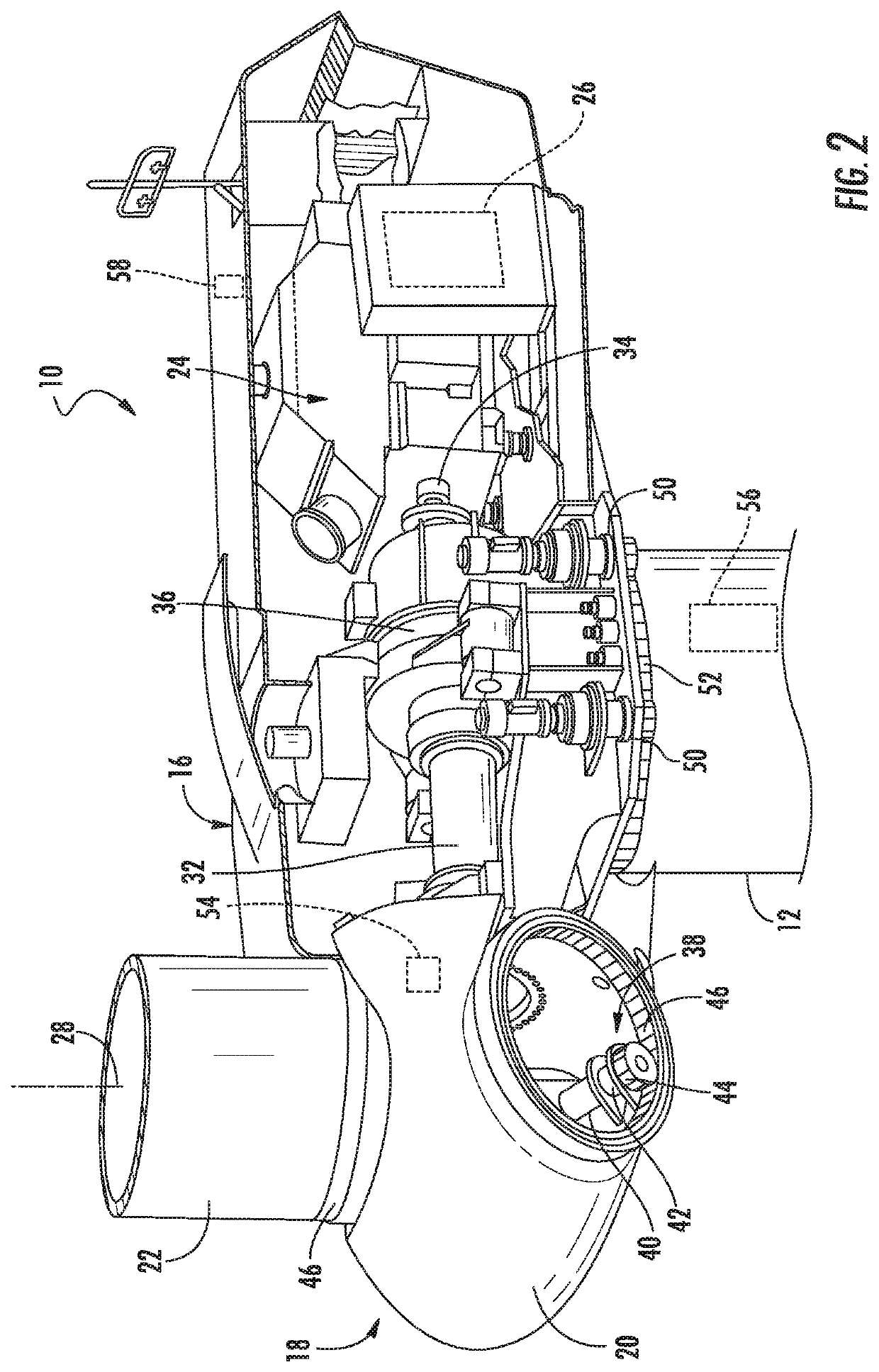
[0026]Reference now will be made in detail to embodiments of the invention, one or more examples of which are illustrated in the drawings. Each example is provided by way of explanation of the invention, not limitation of the invention. In fact, it will be apparent to those skilled in the art that various modifications and variations can be made in the present invention without departing from the scope or spirit of the invention. For instance, features illustrated or described as part of one embodiment can be used with another embodiment to yield a still further embodiment. Thus, it is intended that the present invention covers such modifications and variations as come within the scope of the appended claims and their equivalents.

[0027]Generally, the present disclosure is directed to a system and method for controlling loads of a wind turbine. The method includes receiving sensor signals from one or more sensors that are indicative of a tilt and / or a displacement of the tower or nac...


PUM


Abstract

A method for controlling loads of a wind turbine includes receiving sensor signals from one or more sensors being indicative of a movement of a nacelle of the wind turbine from a reference point. More particularly, the movement corresponds, at least, to a tilt and / or a displacement of the wind turbine tower and / or nacelle. The method also includes generating a deflection profile of the tower along its overall length from a bottom end to a top end thereof based on the sensor signals. Further, the method includes determining at least one of a thrust or a tower load of the wind turbine from the deflection profile. In addition, the method includes implementing a control action for the wind turbine based on the thrust and / or the tower load.

Description

FIELD[0001]The present invention relates to generally to wind turbines, and more particularly, to a system and method for controlling thrust and / or tower loads of a wind turbine.BACKGROUND[0002]Wind power is considered one of the cleanest, most environmentally friendly energy sources presently available, and wind turbines have gained increased attention in this regard. A modern wind turbine typically includes a tower, a generator, a gearbox, a nacelle, and a rotor having a rotatable hub with one or more rotor blades. The rotor blades capture kinetic energy of wind using known airfoil principles. The rotor blades transmit the kinetic energy in the form of rotational energy so as to turn a shaft coupling the rotor blades to a gearbox, or if a gearbox is not used, directly to the generator. The generator then converts the mechanical energy to electrical energy that may be deployed to a utility grid.[0003]Like most dynamic systems, wind turbines are subject to loads that may detrimental...

Claims


Application Information

Patent Timeline
Patent Type & Authority Applications(United States)
IPC IPC(8): F03D7/04F03D17/00F03D80/80
CPCF05B2260/83F03D80/80F05B2220/30F03D7/0224F05B2270/402F03D7/045F03D7/028F05B2260/84G05B2219/2619F05B2270/331F03D7/0204F05B2270/807G05B2219/2639F05B2270/804F03D17/00F03D7/0276F05B2270/10F05B2240/912F05B2270/802F05B2270/337F05B2260/70F05B2270/808F03D7/0296F05B2270/1095F05B2270/334F03D7/0292Y02E10/728Y02E10/72
Inventor LANDA, BERNARDDANIELSEN, DARREN JOHNSHEPPARD, COLLIN MCKEEKRISTEVA, NIKOLINASHARTZER, SAMUEL BRYANAGARWAL, PRANAV
Owner GENERAL ELECTRIC CO
Learn More