
Eureka
For R&D, Eureka makes reading and utilizing patents & technical documents easy.
Eureka AIR
Designed for self-driven R&D workflows. Generate viable solutions, solve complex R&D challenges, empower your innovation with AI.

Eureka Materials
Designed for material experts only. Revolutionize your material R&D, from search, analyze, to developing new materials.

TechResearch
Generate reliable direction feasibility study reports for your R&D in just a few steps.

TechSeek
Discover and master advanced knowledge NOW. Basics, ideas, possibilities, all at once.

TechMind
As an expert in R&D Theories, TechMind can generates customized viable solutions instantly.

TechRisk
Analyze your overall solution with one click, know your potential R&D risks in advance.

TechMonitor
Get weekly tech updates, stay abreast of the latest tech innovations and key insights.
Developing device and image forming apparatus
- Summary
- Abstract
- Description
- Claims
- Application Information
AI Technical Summary
Benefits of technology
Problems solved by technology
Method used
Image

Examples
first exemplary embodiment
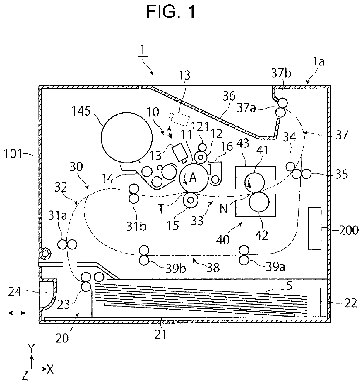
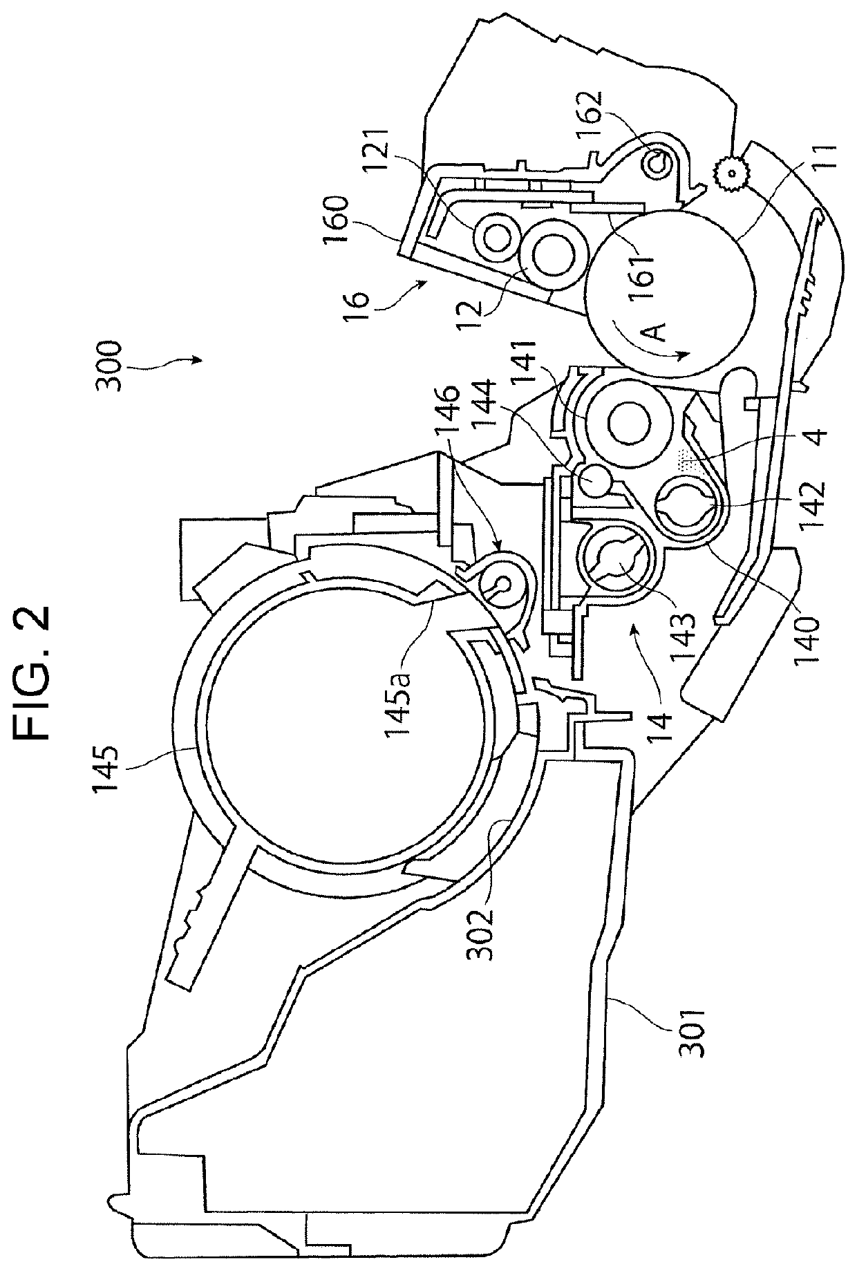
[0034]FIGS. 1 and 2 illustrate an image forming apparatus for which a developing device according to a first exemplary embodiment is used. FIG. 1 schematically illustrates the entirety of the image forming apparatus. FIG. 2 is an enlarged view of part (image forming unit) of the image forming apparatus. In, for example, FIG. 1, an arrow X indicates a depth direction along the horizontal direction, an arrow Y indicates the vertical direction, and an arrow Z indicates a width direction along the horizontal direction.
Overall Structure of the Image Forming Apparatus
[0035]An image forming apparatus 1 according to a first exemplary embodiment is, for example, a monochrome printer. As illustrated in FIG. 1, the image forming apparatus 1 includes an image making device 10, a sheet feed device 20, a transport device 30, a fixing device 40, and so forth. The image making device 10 forms a toner image developed with toner included in developer. The sheet feed device 20 contains required record...
experimental example 2
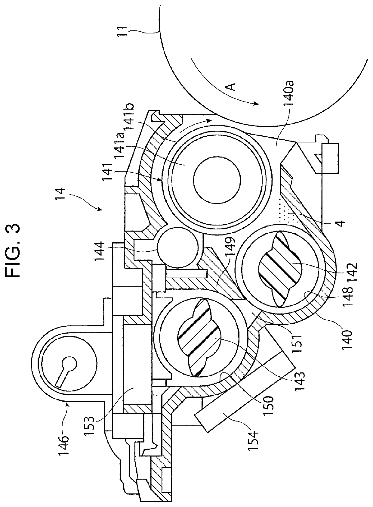
[0096]Next, the developing device 14 as illustrated in FIG. 3 is prototyped, and an experiment in which the density of the developer 4 in the device housing 140 is detected by the toner density sensor 154 is performed. In Experimental Example 2, in order to observe influence of environmental disturbance, an experiment is performed in which the density of the toner is detected while the developing device 14 is being operated under the laboratory environment performed at normal temperature and normal humidity and a high-temperature high-humidity environment.
[0097]FIG. 13 is a graph illustrating results of Experimental Example 2.
[0098]As clearly understood from FIG. 13, in the case of Experimental Example 2, under both a laboratory environment Lab performed at normal temperature and normal humidity and a high-temperature high-humidity environment Az, the output of the toner density sensor 154 substantially linearly increases as the density of the toner increases. Thus, it may be unders...
experimental example 3
[0099]Next, the developing device 14 as illustrated in FIG. 3 is prototyped, and an experiment in which the density of the developer 4 in the device housing 140 is detected by the toner density sensor 154 is performed. Experimental Example 3 checks how the output of the toner density sensor 154 varies when the shape of the permanent magnet 170 and the position where the permanent magnet 170 is mounted are deviated from the design within tolerable ranges.
[0100]Specifically, in Experimental Example 3-1, the shape of the permanent magnet 170 is a central value of the tolerable range and the mounting position of the permanent magnet 170 is a central position of the tolerable range, and in Experimental Example 3-2, the shape of the permanent magnet 170 is a lower limit value of the tolerable range and the mounting position of the permanent magnet 170 is a lower limit position of a target range.
[0101]FIG. 14 is a graph illustrating results of Experimental Example 3.
[0102]As clearly unders...
PUM
 Abstract
Description
Claims
Application Information
 - R&D Engineer
- R&D Manager
- IP Professional
- Industry Leading Data Capabilities
- Powerful AI technology
- Patent DNA Extraction
Browse by: Latest US Patents, China's latest patents, Technical Efficacy Thesaurus, Application Domain, Technology Topic, Popular Technical Reports.
© 2024 PatSnap. All rights reserved.Legal|Privacy policy|Modern Slavery Act Transparency Statement|Sitemap|About US| Contact US: help@patsnap.com