System power monitor

a technology of power monitoring and system power, applied in the direction of gain control, liquid/fluent solid measurement, dc source parallel operation, etc., can solve problems such as difficulty in measuring system power

Active Publication Date: 2020-01-30
ALPHA & OMEGA SEMICON CAYMAN
View PDF5 Cites 10 Cited by
  • Summary
  • Abstract
  • Description
  • Claims
  • Application Information

AI Technical Summary

Benefits of technology

[0008]FIG. 3 is a schematic diagram of an electronic system incorporating one or more system power monitor circuits in embodiments of the present invention.

Problems solved by technology

Measuring system power becomes challenging especially when the system is powered by multiple power supplies.

Method used


Image

  • System power monitor
  • System power monitor
  • System power monitor

Examples


first embodiment

[0031]More specifically, the current scaling operation by the system power monitoring circuits generates scaled power supply output current values that can be used to determine the system power as follows. In a first embodiment, the system power monitoring circuits use a predetermined voltage as the reference voltage VREF. For each power supply providing a power supply output voltage VSX, the power supply output current is scaled by the ratio of VSX / VREF. For the case of two power supplies, the system current ISYS is given as follows:

Isys=IM1+IM2=IS1*VS1VREF+IS2*VS2VREF.

[0032]The system current ISYS represents a single current signal that can be used to determine system power. The system power PSYS can thus be determined as follows:

Psys=VREF*Isys=IS1*VS1+IS2*VS2.

second embodiment

[0033]In a second embodiment, one of the power supplies (e.g. VS1) is selected as the reference voltage VREF. For each of the other power supply providing a power supply output voltage VSX, the power supply output current is scaled by the ratio of VSX / VREF. For the case of two power supplies, the system current ISYS is given as follows:

Isys=IREF+IM2=IREF+IS2*VS2VREF.

[0034]The system current ISYS represents a single current signal that can be used to determine system power. The system power PSYS can thus be determined as follows:

Psys=VREF*Isys=IS1*VS1+IS2*VS2.

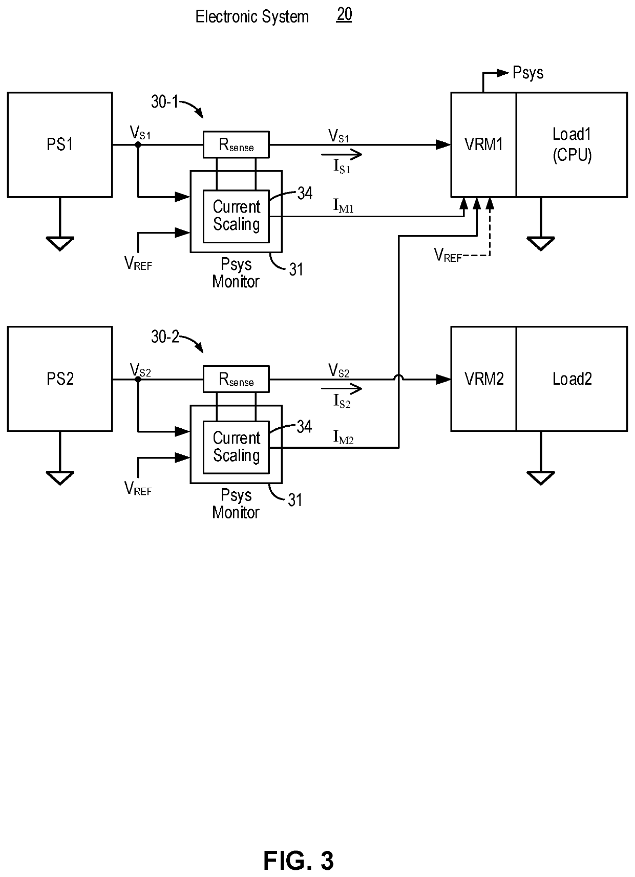
[0035]FIG. 3 is a schematic diagram of an electronic system incorporating one or more system power monitor circuits in embodiments of the present invention. Referring to FIG. 3, a system power monitor circuit 30 is coupled to each power supply to sense the power supply output voltage and the power supply output current and to generate a scaled power supply output current value. For example, a system power monitor circuit 30-1 is...


PUM


Abstract

A system power monitor circuit and method implemented in a system including multiple power supplies measures and scales the power supply output current value at each power supply as a ratio of the power supply output voltage and a reference voltage. Scaled power supply output current values are combined to provide a single system current signal that is referenced to the same reference voltage value being the system voltage signal. The system power is determined from the system current signal and the system voltage signal. In some embodiment, a power supply output voltage of a selected power supply is used as the reference voltage.

Description

FIELD OF THE INVENTION[0001]The invention relates to power monitoring for electronic systems and, in particular, to a system and method for monitoring power consumption in a system with multiple power sources.BACKGROUND OF THE INVENTION[0002]A power module for an electronic system receives power from a power source and delivers regulated voltage or current to components of the electronic system. Typically, the power module is constructed as a voltage regulator which includes a voltage regulator controller and power switching devices. For example, the voltage regulator may be a DC-to-DC converter and delivers a regulated DC voltage to the load.[0003]In a typical configuration, an electronic system may include multiple power modules delivering power to different components of the electronic system. For example, an electronic system may include multiple processors or central processing units (CPU) where each processor is coupled to a respective power module to receive a regulated input...

Claims


Application Information

Patent Timeline
Patent Type & Authority Applications(United States)
IPC IPC(8): G06F1/28H03G3/30H02J4/00G06F1/26
CPCG06F1/28H02J4/00G06F1/263H03G3/30H02J1/10G06F1/305H03G3/007
Inventor YOUNG, CHRIS M.
Owner ALPHA & OMEGA SEMICON CAYMAN
Why Eureka
Try Eureka