Counter flow heat exchanger
- Summary
- Abstract
- Description
- Claims
- Application Information
AI Technical Summary
Benefits of technology
Problems solved by technology
Method used
Image

Examples
Embodiment Construction
[0027]A detailed description of one or more embodiments of the disclosed apparatus and method are presented herein by way of exemplification and not limitation with reference to the Figures.
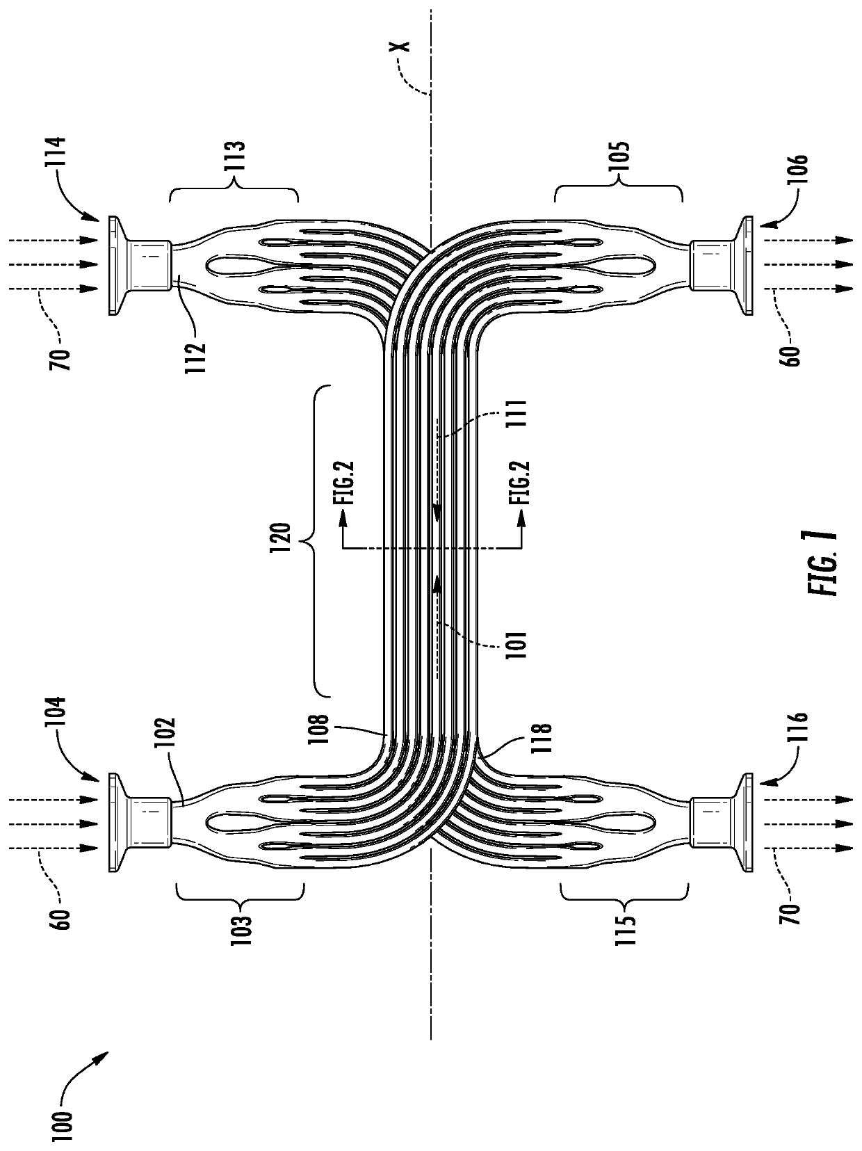
[0028]FIG. 1 is a top view of a counter-flow heat exchanger 100, according to an embodiment of the present disclosure. The counter-flow heat exchanger 100 may be utilized in a variety of applications requiring thermal dynamic transfer of heat including but not limited to an aircraft, a combustion engine, a car, a space craft, a powerplant, a satellite, satellite, etc. In an embodiment, the counter-flow heat exchanger 100 may be utilized in an aircraft. In another embodiment, the counter-flow heat exchanger 100 may be utilized in an aircraft air conditioning system.
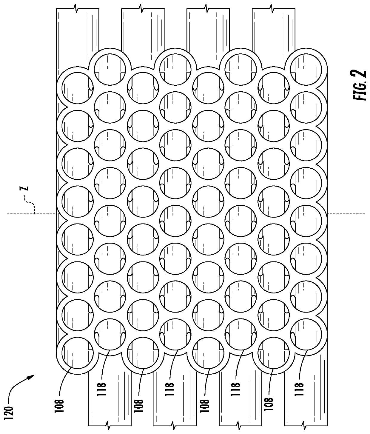
[0029]The counter-flow heat exchanger 100 includes a heat exchanger core 120 that may be oriented along a longitudinal axis X. The counter-flow heat exchanger 100 includes a primary flow passageway 102 and a secondary flow passageway 11...
PUM
 Abstract
Description
Claims
Application Information