Supercharge Your Innovation With Domain-Expert AI Agents!

Head mounted display and multiple depth imaging apparatus

a display and imaging apparatus technology, applied in the field of head mounted display and imaging apparatus thereof, can solve the problems of visual fatigue, dizziness and double vision, nausea, vomiting, etc., and achieve the effect of lowering influences

Active Publication Date: 2020-02-06
HTC CORP
View PDF1 Cites 2 Cited by
  • Summary
  • Abstract
  • Description
  • Claims
  • Application Information

AI Technical Summary

Benefits of technology

The invention provides a headmounted display with a special device that reduces the feeling of dizziness when looking at images caused by a conflict between two parts of the eye's vision. This device splits the beam of light from multiple images, which are then generated at different depths, to create a more realistic and comfortable experience for the user.

Problems solved by technology

Such phenomenon does not follow the normal visual physiology, and the normal visual physiological function is changed, so that disharmony or even conflicts are caused between accommodation and vergence.
As light rays emitted by a display image of a head mounted display do not provide depth information, when the head mounted display is used for a long time, symptoms such as visual fatigue, dry eyes, dizziness and double vision, photophobia, nausea, vomiting, etc. may begin to appear.

Method used


Image

  • Head mounted display and multiple depth imaging apparatus
  • Head mounted display and multiple depth imaging apparatus
  • Head mounted display and multiple depth imaging apparatus

Examples


Embodiment Construction

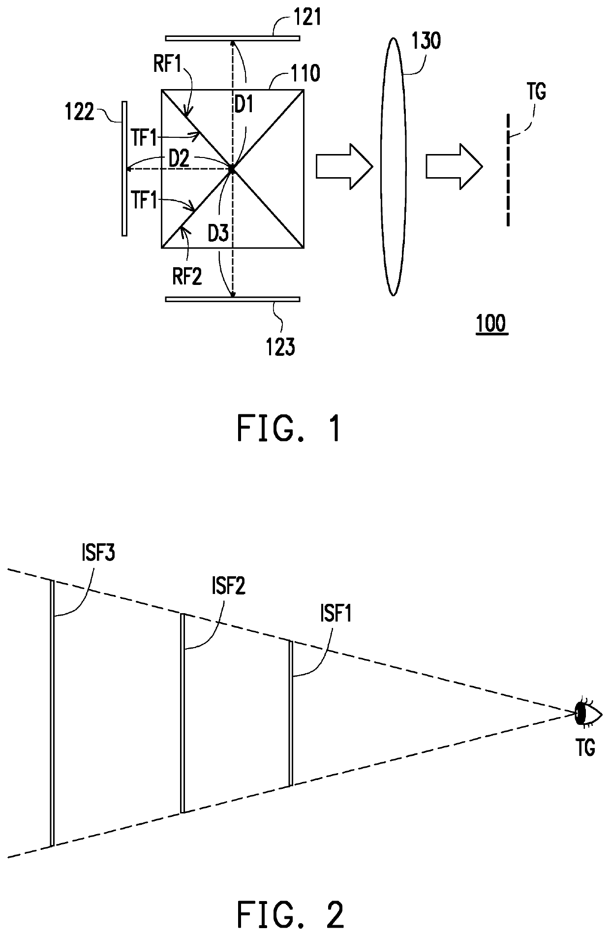
[0016]With reference to FIG. 1, FIG. 1 is a schematic diagram illustrating an imaging apparatus according to an embodiment of the invention. An imaging apparatus 100 includes a beam splitting device 110, displays 121, 122, and 123, and a lens set 130. The beam splitting device 110 has a first reflective surface RF1, a second reflective surface RF2, and a transmissive surface TF1. The display 121 is configured to project a first image to the first reflective surface RF1, and the first reflective surface RF1 then projects the first image, so that the first image is projected to the target area TG. The display 122 is configured to project a second image towards the transmissive surface TF1, and the second image passes through the transmissive surface TF1 of the beam splitting device 110 to be projected to the target area TG. The display 123 projects a third image to the second reflective surface RF2 of the beam splitting device 110, and the second reflective surface RF2 then reflects t...


PUM


Abstract

A head mounted display and a multiple depth imaging apparatus thereof are provided. The imaging apparatus includes a beam splitting device, a first display, a second display, a third display and a lens set. The beam splitting device has a first reflective surface, a second reflective surface and a transmissive surface. The first display projects a first image to the first reflective surface. The second display projects a second image to the transmissive surface. The third display projects a third image to the second reflective surface. The lens set is disposed between the beam splitting device and a target area. The first image, second image and third image are respectively imaging on a first imaging surface, a second imaging surface and a third imaging surface, and distances between the target area and the first, second and third imaging surfaces are different.

Description

CROSS-REFERENCE TO RELATED APPLICATION[0001]This application claims the priority benefit of U.S. provisional application Ser. No. 62 / 712,987, filed on Aug. 1, 2018. The entirety of the above-mentioned patent application is hereby incorporated by reference herein and made a part of this specification.BACKGROUNDTechnical Field[0002]The invention relates to a head mounted display and an imaging apparatus thereof, and more particularly relates to a head mounted display having a multiple depth imaging apparatus.Description of Related Art[0003]In the field of technology nowadays, a three-dimensional image makes use of vergence movements of the eyes, so that an image recognized by the brain appears in space, and a sense of space with depth is thereby formed. After two images with binocular parallax generated in the virtual environment are projected to the retinas of the eyes of the user, the lines of sight, similar to being in the real world, may focus on random virtual objects in the virt...

Claims


Application Information

Patent Timeline
IPC IPC(8): G02B27/01G02B27/14G02B27/09
CPCG02B27/142G02B27/0955G02B27/0172G02B2027/0185G02B30/52
Inventor CHOI, IOK KANDING, LING-YICHEN, YU-HENGYANG, PO-SEN
Owner HTC CORP
Features
  • R&D
  • Intellectual Property
  • Life Sciences
  • Materials
  • Tech Scout
  • Unparalleled Data Quality
  • Higher Quality Content
  • 60% Fewer Hallucinations
Learn More