
Backlight module and input device

a backlight module and input device technology, applied in the direction of instruments, planar/plate-like light guides, mechanical devices, etc., can solve the problems of poor visual effects and uneven brightness, and achieve the effect of uniform optical effects

Active Publication Date: 2020-02-06
LITE ON ELECTRONICS (GUANGZHOU) LTD +1
View PDF16 Cites 4 Cited by
  • Summary
  • Abstract
  • Description
  • Claims
  • Application Information

AI Technical Summary

Benefits of technology

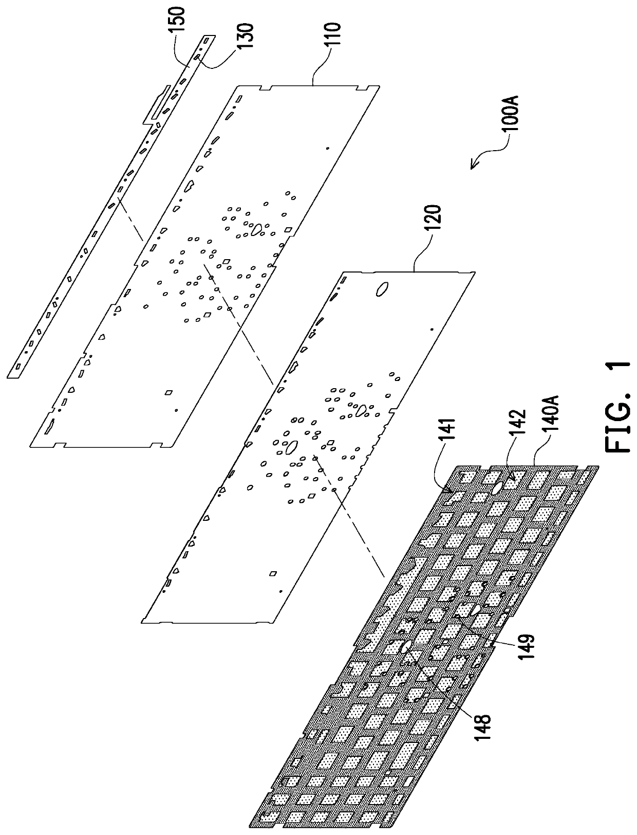
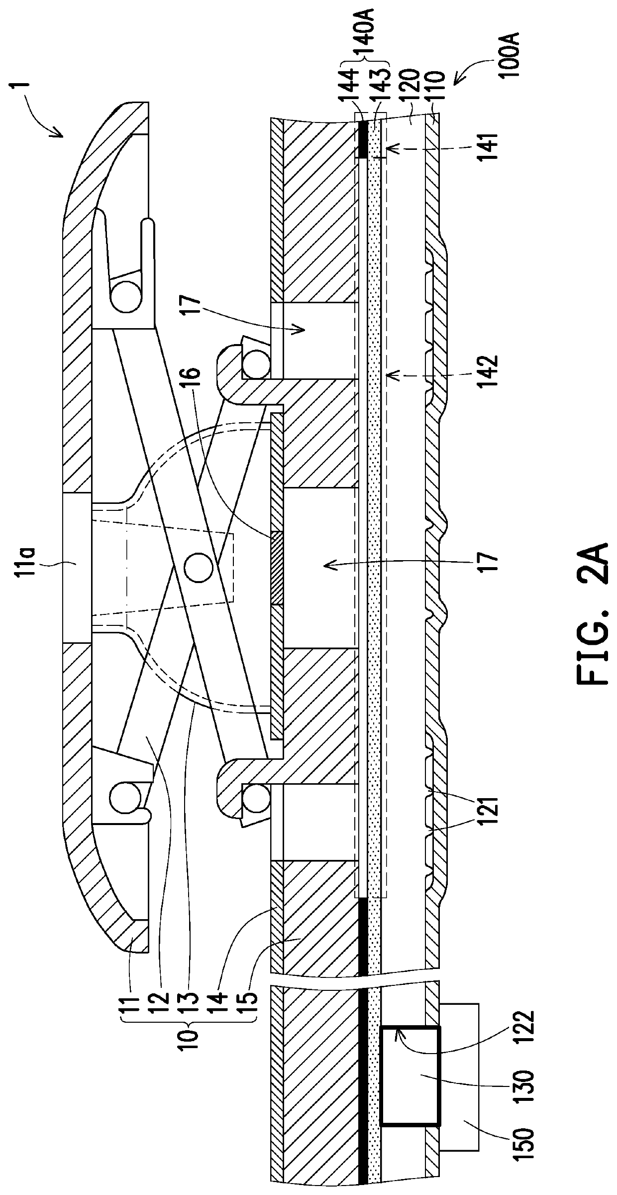
The present patent aims to improve the optical effect of a backlight module by creating a uniform brightness across the entire diffusing elements. By placing a shading plate with a translucent area under the key structure, the over-brightness problem is softened, resulting in a more even distribution of light. This avoids non-uniform brightness caused by the arrangement of the light source and diffusing elements. Therefore, the backlight module and input device of the present patent deliver a more consistent and uniform backlighting.

Problems solved by technology

However, a specific area of the illuminated key is particularly brighter due to the arrangement of the backlight module, resulting in uneven brightness and poor visual effects.

Method used


Image

  • Backlight module and input device
  • Backlight module and input device
  • Backlight module and input device

Examples


Embodiment Construction

[0032]Reference will now be made in detail to the exemplary embodiments of the present disclosure. Examples of the exemplary embodiments are illustrated in the accompanying figures. Whenever possible, the same reference symbols are used in the drawings and descriptions to denote the same or similar parts.

[0033]In embodiments of the disclosure, the backlight module of the illuminated keyboard includes a shading plate to block unwanted light. The shading plate is a light transmitting material coated with a dark-colored coating thereon to define the shading areas from the light transmitting areas which light can pass through. As the light transmitting areas are spaced apart from the light source in different distances, the brightness of the light emitted from the backlight module is nonuniform. Some of the light transmitting areas closer to the light source provide brighter luminance, and some of the light transmitting areas relatively far from the light source provide lower luminance....


PUM

PropertyMeasurementUnit
transmittanceaaaaaaaaaa

Abstract

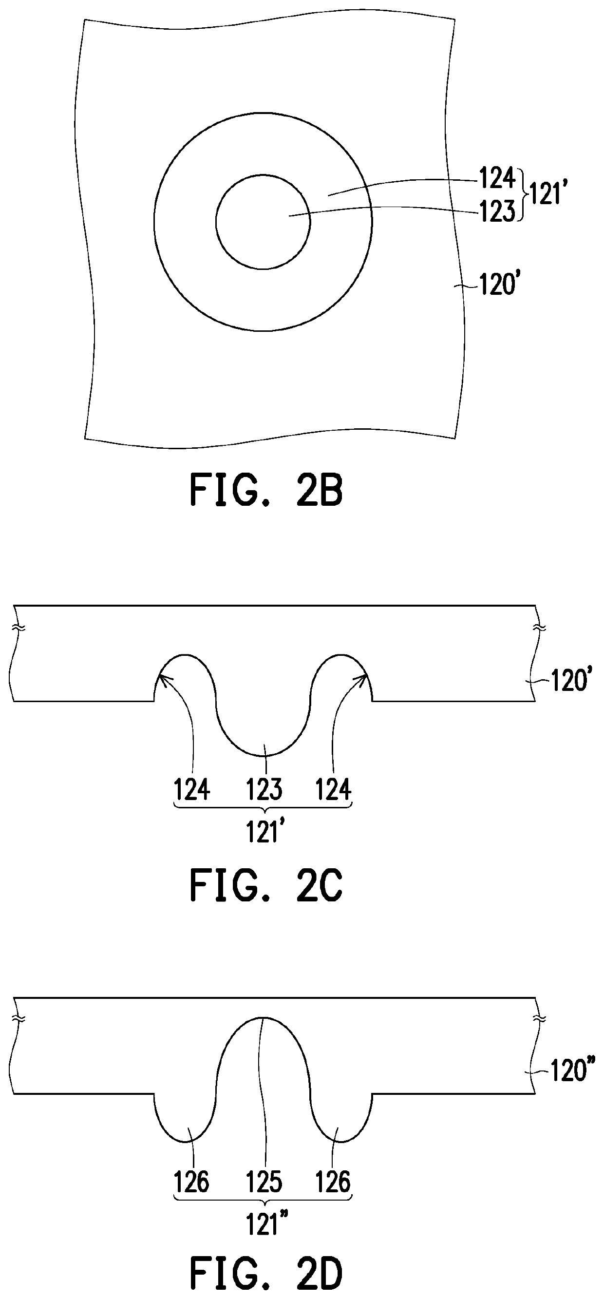
The disclosure provides a backlight module and an input device, wherein the backlight module is adapted to be arranged under a bracket of the input device. The backlight module includes a reflector, a light guide plate, a light source, and a shading plate. The light guide plate is disposed on the reflector and includes a plurality of diffusing elements. The light source is located on a light incident side of the light guide plate. The shading plate is disposed on the light guide plate. The shading plate has a shading area and a translucent area. The diffusing elements are arranged corresponding to the translucent area, wherein a transmittance of the translucent area is greater than a transmittance of the shading area. The scattering or diffusing particles are arranged in the translucent area.

Description

CROSS-REFERENCE TO RELATED APPLICATION[0001]This application claims the priority benefits of U.S. provisional application Ser. No. 62 / 712,993, filed on Aug. 1, 2018, U.S. provisional application Ser. No. 62 / 808,818, filed on Feb. 21, 2019, and China application serial no. 201910490046.9, filed on Jun. 6, 2019. The entirety of each of the above-mentioned patent applications is hereby incorporated by reference herein and made a part of this specification.BACKGROUNDTechnical Field[0002]The disclosure relates to a backlight module and an input device, and in particular to a backlight module and an input device with enhanced brightness uniformity.Description of Related Art[0003]With the development of technology, electronic devices are designed to be lighter and thinner, and creating visual interest is an upward trend. Taking keys as an example, illuminated keys have been developed to increase aesthetics or visibility. In general, the illuminated keys could be obtained by placing a backl...

Claims


Application Information

Patent Timeline
Patent Type & Authority Applications(United States)
IPC IPC(8): G06F3/02F21V8/00
CPCG06F3/0202G02B6/0055G02B6/0051G02B6/005H01H13/83G02B6/006H01H2219/062H01H2219/056H01H2219/06H01H2219/044H01H2219/066
Inventor CHENG, CHING-LUNG
Owner LITE ON ELECTRONICS (GUANGZHOU) LTD
Learn More