System and method to provide optimal polling of devices for real time data

a technology of real-time data and polling method, applied in the field of components control, can solve problems such as substantial system delays and low frequency of polling

Active Publication Date: 2020-02-06
DELL PROD LP
View PDF2 Cites 2 Cited by
  • Summary
  • Abstract
  • Description
  • Claims
  • Application Information

AI Technical Summary

Benefits of technology

[0003]A system for polling components is disclosed that includes a plurality of processors and a control system configured to interface with each of the plurality of processors, and to 1) poll each of t

Problems solved by technology

Polling devices can result in substantial system delays when devices become inoperative and

Method used


Image

  • System and method to provide optimal polling of devices for real time data
  • System and method to provide optimal polling of devices for real time data
  • System and method to provide optimal polling of devices for real time data

Examples


Embodiment Construction

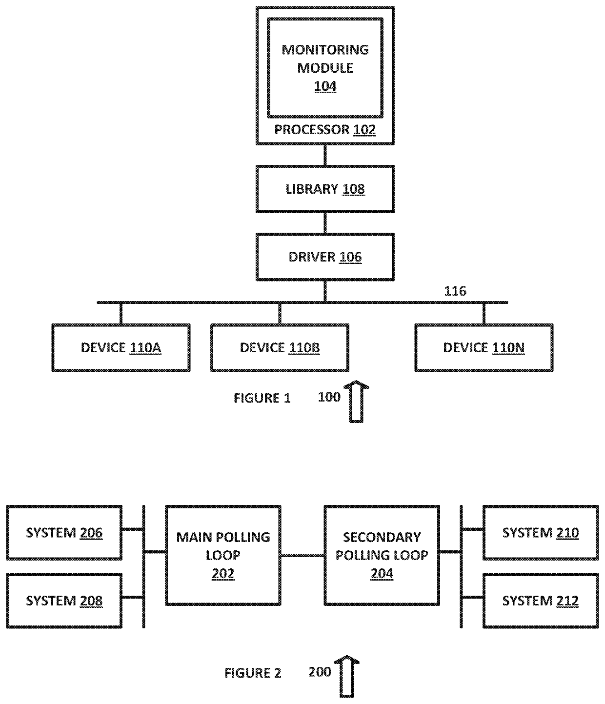
[0013]In the description that follows, like parts are marked throughout the specification and drawings with the same reference numerals. The drawing figures may be to scale and certain components can be shown in generalized or schematic form and identified by commercial designations in the interest of clarity and conciseness.

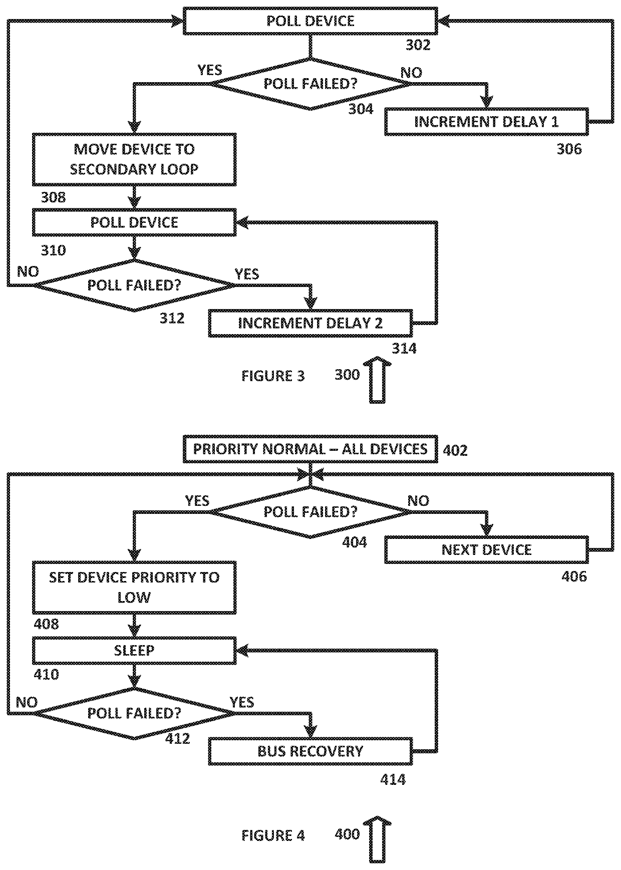
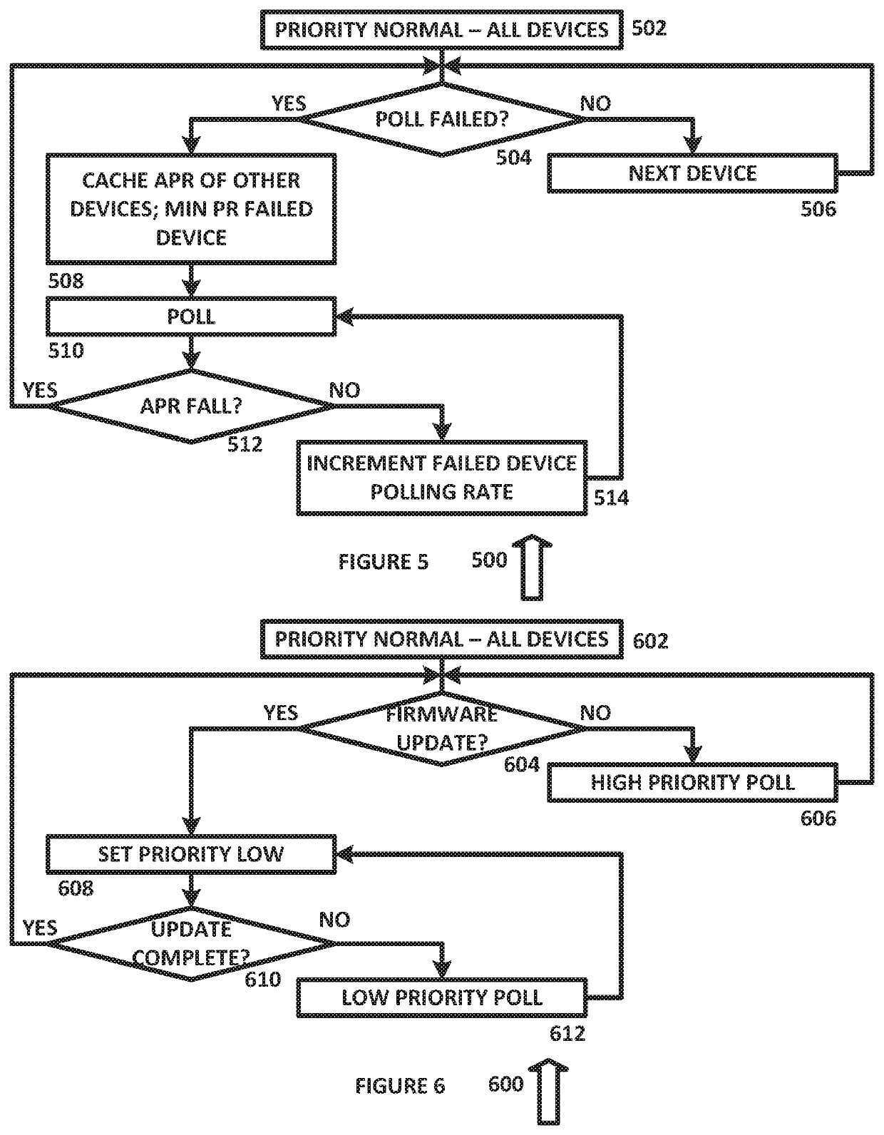
[0014]A polling module can be used in a real-time system to poll the status of the devices of the system. These devices can be inter-integrated circuit (I2C) devices or other suitable devices, and can be continuously polled at discrete intervals to obtain real-time status data. In such cases, there could be one or more devices that fail and which do not respond to the poll, resulting in a timeout condition. A continuing timeout condition will affect the polling of devices that are working from getting or providing real time data.

[0015]To address this condition, I2C bus and device recovery can be automatically triggered after I2C timeout or other error conditions...


PUM


Abstract

A system for polling components is disclosed that includes a plurality of processors and a control system configured to interface with each of the plurality of processors, and to 1) poll each of the plurality of processors using a first polling loop and 2) transfer one of the plurality of processors to a second polling loop if the one of the plurality of processors is non-responsive to the poll.

Description

TECHNICAL FIELD[0001]The present disclosure relates generally to control of components within a complex system, and more specifically to a system and method to provide optimal polling of devices for real time data.BACKGROUND OF THE INVENTION[0002]Polling devices can result in substantial system delays when devices become inoperative and do not respond to polls. As a result, polling is not frequently used because of such problems.SUMMARY OF THE INVENTION[0003]A system for polling components is disclosed that includes a plurality of processors and a control system configured to interface with each of the plurality of processors, and to 1) poll each of the plurality of processors using a first polling loop and 2) transfer one of the plurality of processors to a second polling loop if the one of the plurality of processors is non-responsive to the poll.[0004]Other systems, methods, features, and advantages of the present disclosure will be or become apparent to one with skill in the art...

Claims


Application Information

Patent Timeline
IPC IPC(8): G06F11/30G06F8/65
CPCG06F11/3055G06F11/3027G06F11/3072G06F8/65G06F11/3051G06F8/654G06F9/4411G06F11/0757
Inventor MADDUKURI, AKKIAH CHOUDARYMUTHAIYAN, ARUNDHOTE, KOMAL KUMARBISA, RAMA RAO
Owner DELL PROD LP
Why Eureka
Try Eureka