
Tile structure of shape-adaptive phased array antenna

a phased array antenna and shape-adaptive technology, which is applied in the field of shape-adaptive phased array antennas, can solve the problems of affecting the performance of active phased array antennas, so as to achieve the effect of improving the performance of the active phased array and minimizing the structural interferen

Active Publication Date: 2020-02-06
AGENCY FOR DEFENSE DEV
View PDF2 Cites 0 Cited by
  • Summary
  • Abstract
  • Description
  • Claims
  • Application Information

AI Technical Summary

Benefits of technology

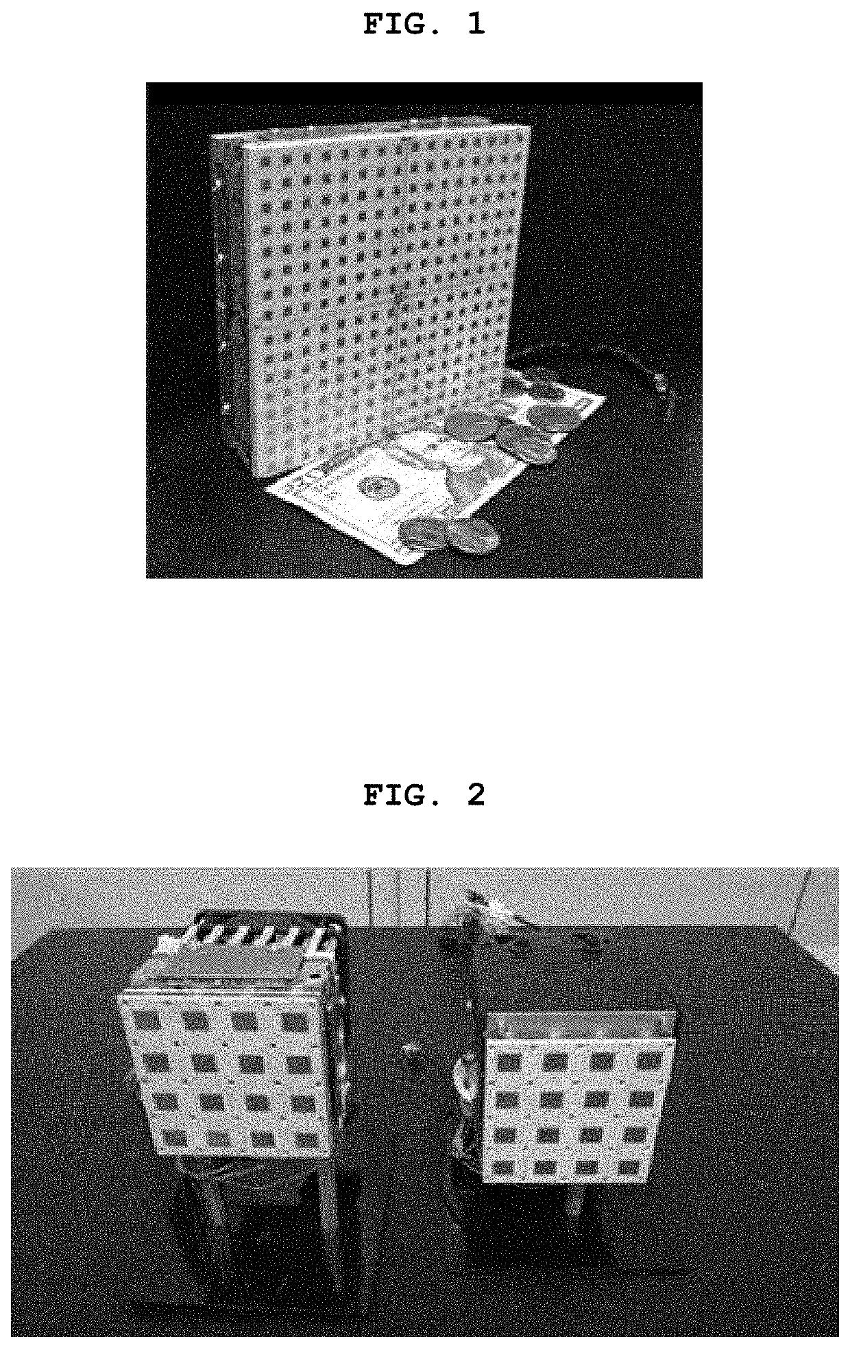
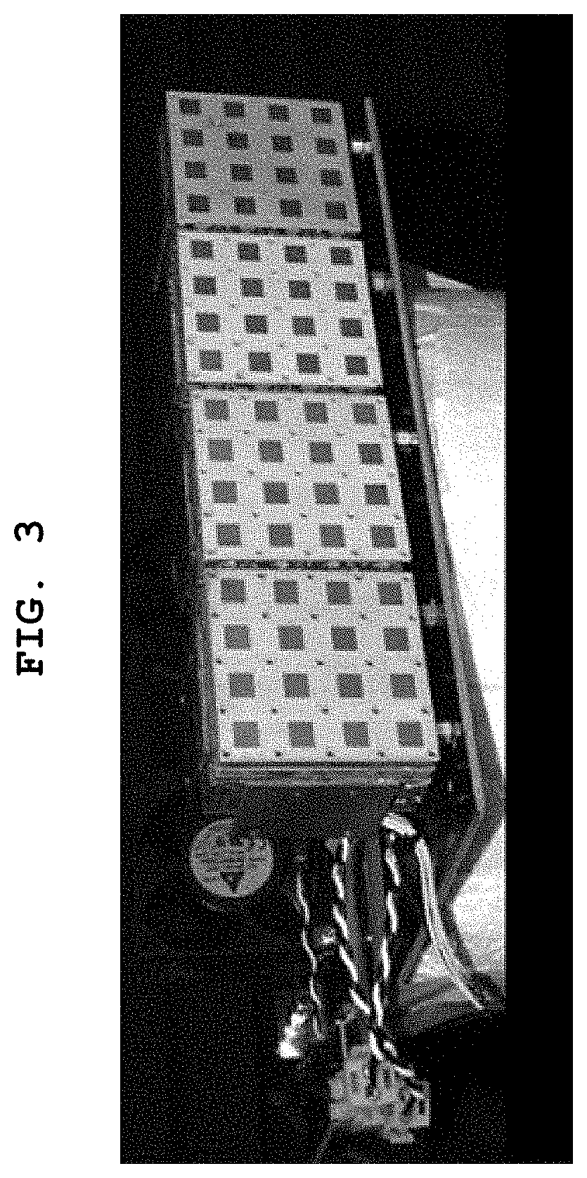
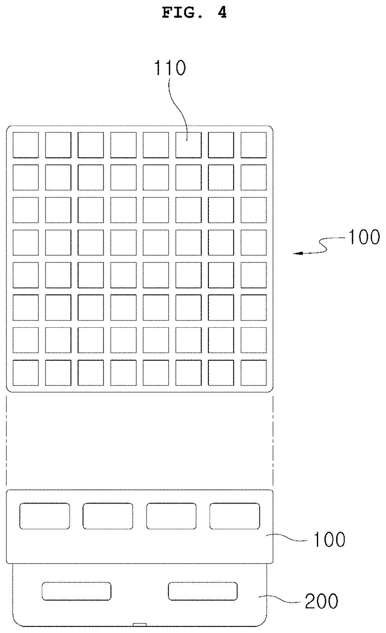
The present invention provides a tile structure for a shape-adaptive phased array antenna that has a "T" shape. The lower part of the "T" is narrower than the upper part to minimize interference between adjacent tiles, ensuring better performance and continuous arrangement of the antenna. The upper and lower tiles can also be changed in size to match various curved surface shapes. Overall, this make the antenna easier to install and more flexible in its application.

Problems solved by technology

Thus, costs, weight and volume of the transceiver modules are important considerations when developing an entire radar system.
On the other hand, the tile-type structure having the same scale is more difficult to utilize when implementing the phased array antenna than the brick-type structure.
However, when arranging the antenna in a curved surface structure to adapt a shape, a structural interference occurs between the tiles.
Thereby, the active phased array antenna exhibits a degradation in performance such as a reduction in an electrical beam steering performance, an increase in side-lobes of a beam pattern, and the like.

Method used


Image

  • Tile structure of shape-adaptive phased array antenna
  • Tile structure of shape-adaptive phased array antenna
  • Tile structure of shape-adaptive phased array antenna

Examples


Embodiment Construction

[0028]The present invention may be altered in various ways and have various embodiments, and will be described with reference to the drawings for illustrating specific embodiments.

[0029]However, the present invention is not limited to the specific embodiments, and it will be understood by those skilled in the art that the present invention is to cover all modifications, equivalents, and alternatives falling within the spirit and scope of the present invention. Referring to the drawings, wherein like reference characters designate like or corresponding parts throughout the several views.

[0030]It will be understood that when a component is referred to as being “connected to” or “coupled to” another component, it can be directly connected or coupled to the other component intervening another component may be present. In contrast, when a component is referred to as being “directly connected to” or “directly coupled to” another component, there is no intervening component present.

[0031]I...


PUM


Abstract

The present invention relates to a tile structure of a shape-adaptive phased array antenna, and more specifically to a tile structure of a shape-adaptive phased array antenna configured to improve drag and low-observable properties of an airplane, and minimize a structural interference between adjacent tiles of the phased array antenna.

Description

CROSS-REFERENCE TO RELATED APPLICATION[0001]Pursuant to 35 U.S.C. § 119(a), this application claims the benefit of earlier filing date and right of priority to Korean Application No. 10-2018-0090039 filed on Aug. 1, 2018, the contents of which is incorporated by reference herein in its entirety.BACKGROUND OF THE INVENTION1. Field of the Invention[0002]The present invention relates to a tile structure of a shape-adaptive phased array antenna, and more specifically, to a tile structure of a shape-adaptive phased array antenna configured to improve drag and low-observable properties of an airplane, and minimize a structural interference between adjacent tiles of the phased array antenna.2. Background of the Invention[0003]Currently, a radar system is considered as a kind of weapon system due to a plurality of complex functions provided therein. Therefore, in order to implement various functions in one radar system, the radar system is made to be highly compact and smaller.[0004]Accordi...

Claims


Application Information

Patent Timeline
Patent Type & Authority Applications(United States)
IPC IPC(8): H01Q1/28H01Q21/00H01Q21/29H01Q21/06
CPCH01Q1/282H01Q21/061H01Q21/293H01Q21/0025H01Q1/286H01Q3/26H01Q21/065
Inventor JOO, TAE HWANSEO, JONG WOORYU, JI HOKIM, KI CHULHWANG, CHAN HOKIM, MIN SUNGLEE, CHEOL HOON
Owner AGENCY FOR DEFENSE DEV
Learn More