Headlight system for a vehicle

a headlight system and vehicle technology, applied in the direction of signalling/lighting devices, vehicle components, lighting and heating apparatus, etc., can solve the problems of easy to see non-uniform color caused by dispersion, not cost-effective, etc., and achieve the effect of eliminating or at least alleviating one or mor

Active Publication Date: 2020-02-13
LUMILEDS
View PDF7 Cites 2 Cited by
  • Summary
  • Abstract
  • Description
  • Claims
  • Application Information

AI Technical Summary

Benefits of technology

[0006]The present invention provides a front-lighting system for a vehicle, so as to eliminate or at least alleviate one or more of the above mentioned disadvantages.
[0012]As part of the invention, the transparent shutter also comprises a light out-coupling surface, at which light is out-coupled towards the secondary optics. The light out-coupling surface is designed to be flat or in a free form, thus allowing change in an out-coupling angle and distribution of the output light. The transparent shutter further also comprises micro-optical surfaces adjacent to the above mentioned light out-coupling surface. With these micro-optical surfaces such as tooth-like surfaces included, light that would be otherwise total-internally reflected and got lost within the transparent shutter becomes capable of being refracted towards the secondary optics, thus improving the usage of light.
[0014]Within the above proposed front-lighting system for a vehicle, a transparent, and further optionally fixed, shutter is used, which will lead to no shading of the light transmission. Besides, through a suppression action on a lower part of light from the first light source by the transparent shutter, a clear cut-off line can be created in the final projected low beam pattern. In this case, the dark area between the two beams, such as the high beam and the low beam, caused by any normal opaque shutter can be avoided.
[0016]According to another embodiment of the above front-lighting system, the transparent shutter is further designed to project the light received from the second light source via the second primary optics onto the secondary optics through total internal reflection. A total internal reflection in the transparent shutter helps to fold the light path, so as to keep the first light source and the second light source, such as the low-beam light source and the high-beam light source, away from each other within the whole system. For example, the high-beam light source and the low-beam light source can be located at a distance larger than 20 mm in the system. Obviously, any other different distances may be suitable based on different practices. Further optionally, the spacing between the low-beam light source and the high-beam light source, when mounted in the vehicle, is larger in a horizontal direction than in a vertical direction. In this way, the heat dissipation feasibility can be improved, and the color non-uniformity of the final beam pattern can also be lowered down. As a further preferable instance, the total internal reflection can occur one or more times in the transparent shutter, which facilitates a further reduction in the light path. In this way, one or more of the horizontal or vertical spaces of the front-lighting system can be shortened, and the whole system will become more compact.

Problems solved by technology

Traditionally, in this kind of moveable shutter solution, a solenoid valve is needed to control the moveable shutter 14, which is not cost-effective.
Additionally, a non-uniform color caused by dispersion is often easy to see in this case.

Method used


Image

  • Headlight system for a vehicle
  • Headlight system for a vehicle
  • Headlight system for a vehicle

Examples


Embodiment Construction

[0031]While this invention is susceptible of embodiments in many different forms, there is shown in the drawings and will be described in detail herein one or more specific embodiments, with the understanding that the present description is to be considered as exemplary of the basic principle of the present invention and not intended to limit the present invention to the specific embodiments shown and described herein.

[0032]It should be noted that various components in different figures are not drawn to scale. Besides, relative positions between individual elements shown in the figures are only used to illustrate the basic principle of the present invention and should not be considered to limit the scope of the present invention.

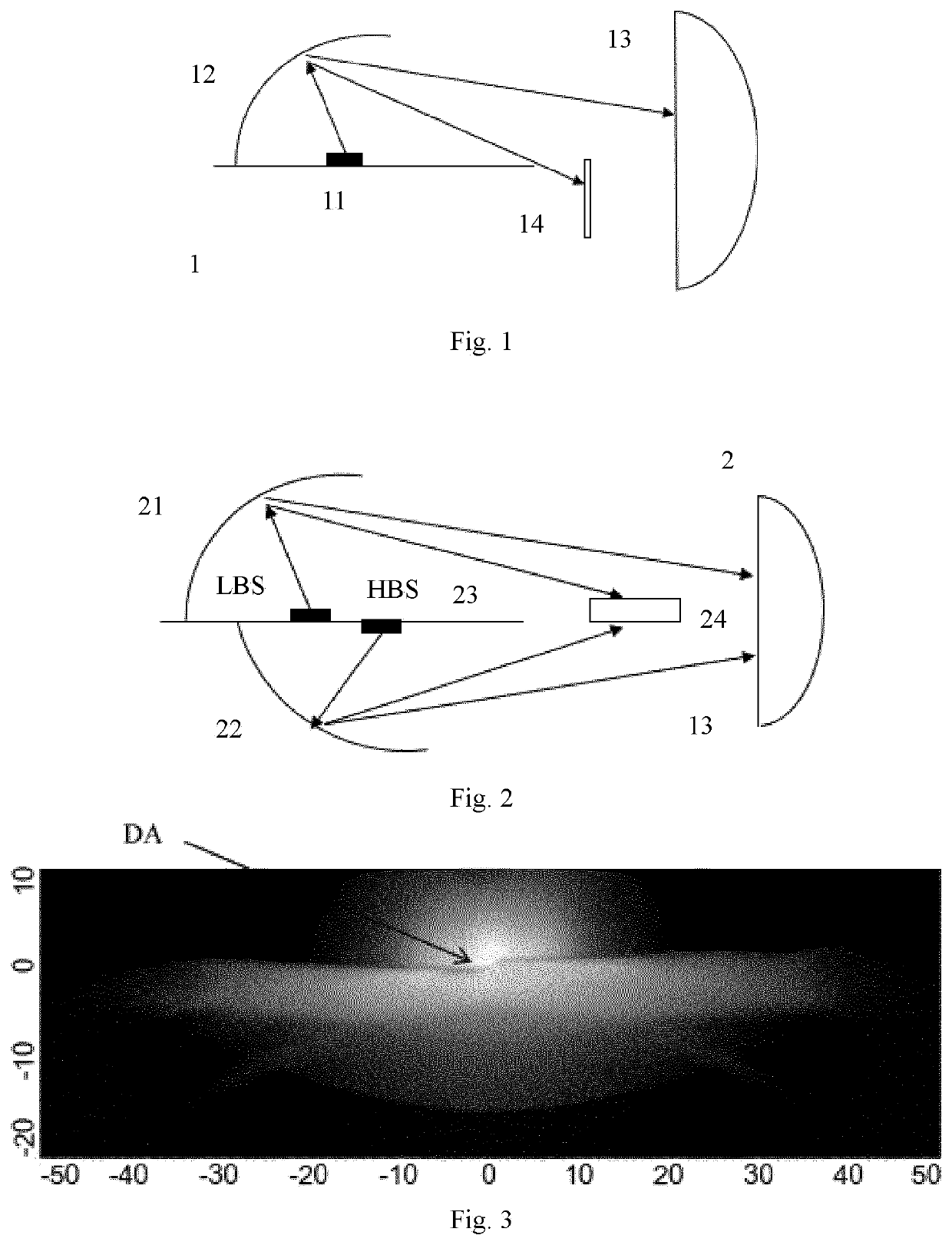
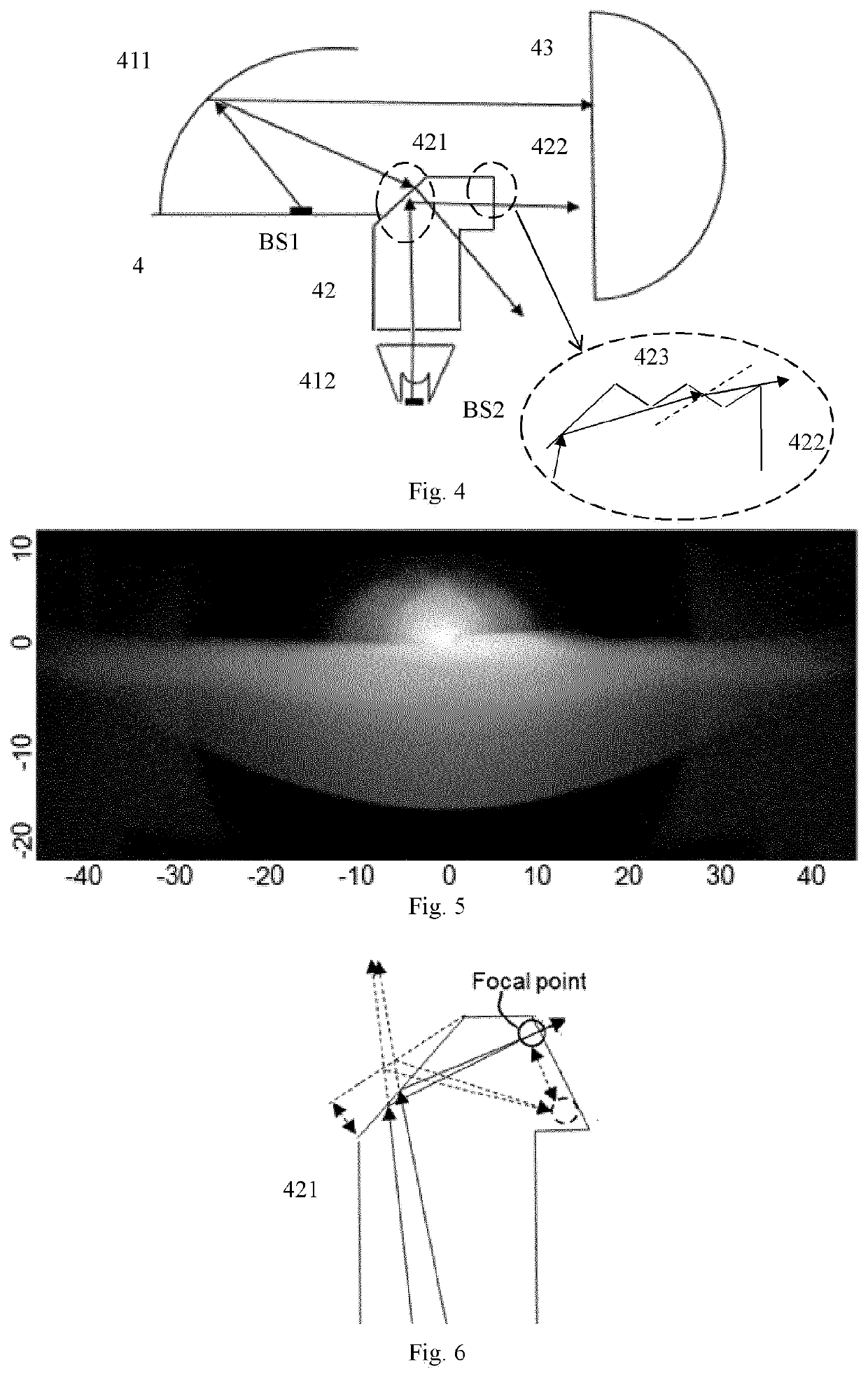
[0033]As discussed in the background section and shown in FIGS. 1-2, an opaque shutter 14, 24 is usually used in the traditional front-lighting systems 1, 2 of a vehicle. This opaque shutter 14, 24 tends to cause a dark area (see DA in FIG. 3) in the final p...


PUM


Abstract

The present invention relates to the field of automotive front-lighting, and particularly to a front-lighting system for a vehicle. The front-lighting system comprises: a first light source, a second light source, a first primary optics, a second primary optics, a transparent shutter, and a secondary optics. The first primary optics is designed to receive light from the first light source and project it onto the transparent shutter and the secondary optics. The second primary optics is designed to receive light from the second light source and project it onto the transparent shutter. The transparent shutter is designed to receive light from the first light source via the first primary optics and prevent a lower part of it from entering the secondary optics. The transparent shutter is further designed to receive light from the second light source via the second primary optics and project it onto the secondary optics. The secondary optics is designed to receive light from the first primary optics and the transparent shutter, and project it onto a road in front of the vehicle. The transparent shutter comprises a flat or freeform light out-coupling surface and micro-optical surfaces adjacent to the light out-coupling surface.

Description

FIELD OF THE INVENTION[0001]The present invention relates to the field of automotive front-lighting, and particularly to a front-lighting system for a vehicle.BACKGROUND OF THE INVENTION[0002]Bi-function Poly-Ellipsoidal System (PES) solution for a headlamp has been widely used in automotive lighting today. Generally speaking, an opaque shutter is utilized to enable switching between a high beam (also known as an upper beam) and a low beam (also known as a lower beam). There are several main approaches to realize such a shutter function. Two most common examples are discussed as follows.[0003]In a first category of examples, a moveable shutter is adopted. As shown in FIG. 1, the front-lighting system 1 in this case may comprise a LED 11, a reflector 12, a projection lens 13 and a moveable shutter 14. Here, LED 11 serves as a common light source for both high beam and low beam. Specifically, the moveable shutter 14 is configured to switch between the low beam and the full high beam. ...

Claims


Application Information

Patent Timeline
Patent Type & Authority Applications(United States)
IPC IPC(8): B60Q1/00F21S41/143F21S41/365F21S41/20F21S41/148F21S41/255
CPCF21S41/143F21S41/365F21S41/285F21S41/148F21W2102/13B60Q1/0058F21S41/255F21S41/24F21S41/395F21S41/32F21S41/43F21S41/663F21W2102/16
Inventor LU, KANGWU, PINGHAN, MENGFENG, HUAYUNLU, YIWEN
Owner LUMILEDS
Why Eureka
Try Eureka