Quantum dot light emitting devices
a light-emitting diode and quantum dot technology, applied in the field of electrical devices, can solve the problems of low light generation efficiency, lack of suitable hole-transport layer (htl) capable of efficient, and high operating voltage of qled devices
- Summary
- Abstract
- Description
- Claims
- Application Information
AI Technical Summary
Benefits of technology
Problems solved by technology
Method used
Image


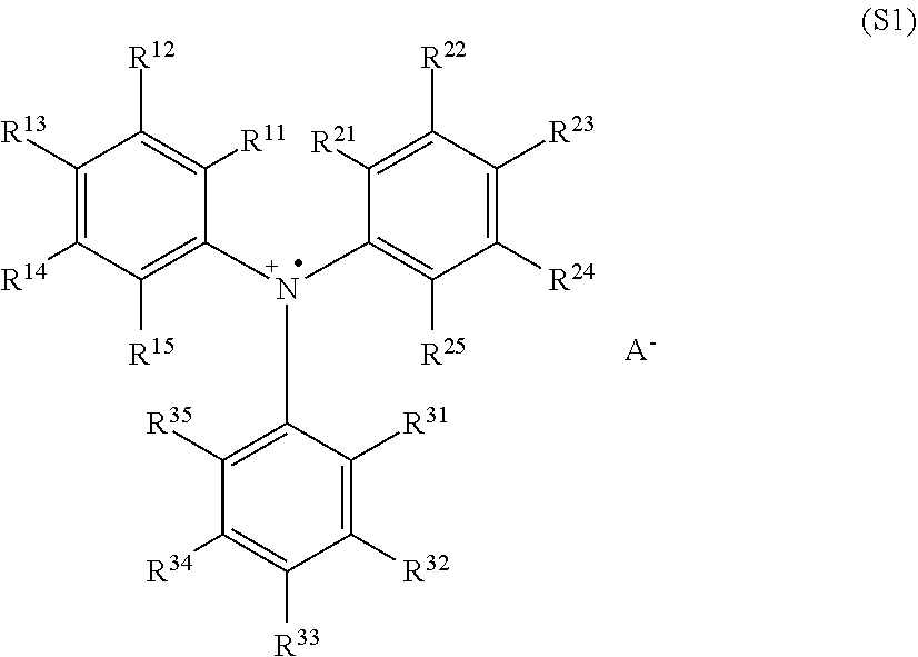
Examples
example 1
Preparative Summary of Synthesis of Monomer S101
[0089]
example 2
Preparative Synthesis of 3-(3-(4-([1,1′-biphenyl]-4-yl(9,9-dimethyl-9H-fluoren-2-yl)amino)phenyl)-9H-carbazol-9-yl)benzaldehyde
[0090]A round bottom flask was charged with carbazole (9.10 g, 15.1 mmol, 1.0 equiv), 3-bromobenzaldehyde (2.11 mL, 18.1 mmol, 1.2 equiv), CuI (0.575 g, 3.02 mmol, 0.2 equiv), potassium carbonate (6.26 g, 45.3 mmol, 3.0 equiv), and 18-crown-6 (399 mg, 10 mol %). The flask was flushed with nitrogen and connected to a reflux condenser. 55 mL of dry, degassed, 1,2-dichlorobenzene was added, and the mixture was heated to 180° C. overnight. Only partial conversion was noted after 14 hours. An additional 2.1 mL of 3-bromobenzaldehyde was added, and heated continuously for another 24 hours.
[0091]The solution was cooled and filtered to remove solids. The filtrate was concentrated and adsorbed onto silica for purification by chromatography (0 to 60% dichloromethane in hexanes), which delivered product as a pale yellow solid (8.15 g, 74%). 1H NMR (500 MHz, CDCl3) δ 1...
example 5
Preparative Measurement of Molecular Weight of Polymer
[0095]Gel permeation chromatography (GPC) studies were carried out as follows. 2 mg of HTL polymer was dissolved in 1 mL THF. The solution was filtered through a 0.2 m polytetrafluoroethylene (PTFE) syringe filter and 50 μl of the filtrate was injected onto the GPC system. The following analysis conditions were used: Pump: Waters™ e2695 Separations Modules at a nominal flow rate of 1.0 mL / min; Eluent: Fisher Scientific HPLC grade THF (stabilized); Injector: Waters e2695 Separations Modules; Columns: two 5 μm mixed-C columns from Polymer Laboratories Inc., held at 40° C.; Detector: Shodex RI-201 Differential Refractive Index (DRI) Detector; Calibration: 17 polystyrene standard materials from Polymer Laboratories Inc., fit to a 3rd order polynomial curve over the range of 3,742 kg / mol to 0.58 kg / mol.
MonomerMnMwMzMz+1Mw / MnS10123,41388,953176,978266,7183.799DaDaDaDa
PUM
| Property | Measurement | Unit |
|---|---|---|
| molecular weight | aaaaa | aaaaa |
| length | aaaaa | aaaaa |
| length | aaaaa | aaaaa |
Abstract
Description
Claims
Application Information
 - R&D Engineer
- R&D Manager
- IP Professional
- Industry Leading Data Capabilities
- Powerful AI technology
- Patent DNA Extraction
Browse by: Latest US Patents, China's latest patents, Technical Efficacy Thesaurus, Application Domain, Technology Topic.
© 2024 PatSnap. All rights reserved.Legal|Privacy policy|Modern Slavery Act Transparency Statement|Sitemap