Method and device for operating a rotary screen-printing machine

a technology of screen printing press and operating device, which is applied in the direction of printing press, rotary presses, printing, etc., can solve the problems of unsatisfactory soiling of the impression cylinder, particularly adverse effect, and build-up of ink, so as to reduce reduce the cost and effort of cleaning the impression cylinder and/or the risk of damage, and reduce the risk of printing ink. , the effect of reducing the operating speed

Active Publication Date: 2020-02-20
KOENIG & BAUER AG
View PDF0 Cites 0 Cited by
  • Summary
  • Abstract
  • Description
  • Claims
  • Application Information

AI Technical Summary

Benefits of technology

[0010]The advantages to be achieved with the invention involve, in particular, a substantial reduction in the cost and effort of cleaning the impression cylinder and / or in the risk of damage to the screen printing forme. As a result of the throw-on sequence, printing ink that accumulates on the outer surface of the screen printing forme while the screen printing cylinder is thrown off is removed before the built-up ink can be distributed to unintended locations on the sheet and / or the impression cylinder as a result of the engagement of the squeegee. As a further advantage, the forcing through of printing ink can be reduced by lower operating speeds in the print-off stage.

Problems solved by technology

When the screen printing cylinder is thrown off, a lack of ink removal along with possible rotation may result in an undesirable build-up of ink on the outer surface of the screen, and when thick layers come into contact with the impression cylinder surface or during printing of the first sheets, this can ultimately lead to undesirable soiling of the impression cylinder.
This effect is particularly adverse when an intermediate drying step is carried out by means of a dryer directed toward the lateral surface of the cylinder.
This leads rapidly to a build-up of ink.
During intermediate drying, in particular, the dried ink becomes hard, forming peaks, and can cause damage to the screen printing forme.
Printing ink that is hardened in this way is very difficult to remove from the cylinder surface.

Method used


Image

  • Method and device for operating a rotary screen-printing machine
  • Method and device for operating a rotary screen-printing machine
  • Method and device for operating a rotary screen-printing machine

Examples


Embodiment Construction

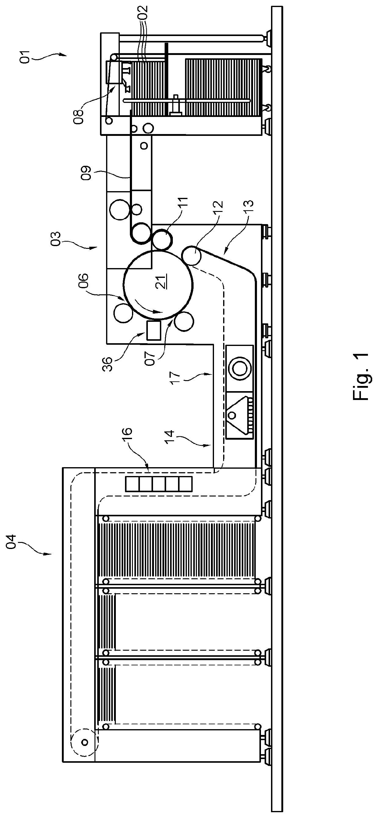
[0024]A printing press, e.g., a sheet-fed printing press or a web-fed printing press, comprises on the intake side an infeed device 01, which supplies the printing press with a sheet-format or web-format printing substrate 02, at least one printing assembly 03, with which the printing substrate 02 is printed one or more times on one side or on both sides, and a product delivery 04, where printed products or intermediate products are delivered in stacks or continuously, or are wound onto a roll (see, e.g., FIG. 1).

[0025]In a preferred embodiment illustrated in the figures, the printing press is embodied as a printing press for security printing, for example, for printing onto web-format printing substrate 02, e.g. a printing substrate web, or preferably for printing onto sheet-format printing substrate 02, e.g. printing substrate sheets 02. Infeed device 01 for the latter embodiment is configured, e.g., as a sheet feeder 01, in which a pile of the printing substrate sheets 02 to be f...


PUM


Abstract

A screen-printing unit in a printing machine comprises a screen cylinder which carries a screen-printing stencil and in which a squeegee is moved, from the inside, into contact with, and away from the screen-printing stencil. The screen cylinder is moved into contact with an impression cylinder, such that a printing position is formed, and is moved away therefrom, such that a gap is formed. The screen cylinder is moved away from the impression cylinder, in a first phase, when the squeegee is in a non-contacting position. In a second phase, at least one sheet of printing material is passed through the printing position when the squeegee continues to be in a non-contacting position and the screen cylinder is at least temporarily in a contacting position. For subsequent sheets of printing material, in a third phase, the screen-printing unit is operated with the squeegee one of permanently and cyclically, such as at least once for each sheet of printing material, in a contacting position.

Description

CROSS REFERENCE TO RELATED APPLICATIONS[0001]This application is the U.S. National Phase, under 35 U.S.C. § 371, of PCT / EP2017 / 074032, filed Sep. 22, 2017; published as WO 2018 / 153509 A1 on Aug. 30, 2018, and claiming priority to DE 10 2017 202 941.2, filed Feb. 23, 2017, the disclosures of which are expressly incorporated herein in their entireties by reference.FIELD OF THE INVENTION[0002]The present invention relates to a method and a device for operating a screen printing press. A screen printing unit in the screen printing press includes a screen cylinder which carries a screen printing forme and in which screen cylinder, a squeegee can be engaged, from the inside, against the screen printing forme and can be disengaged therefrom. The screen cylinder can be thrown onto an impression cylinder, such that a print position is formed, and can be thrown off of the impression cylinder such that a gap is formed. The squeegee can be engaged against the screen printing forme and can be di...

Claims


Application Information

Patent Timeline
Patent Type & Authority Applications(United States)
IPC IPC(8): B41F15/08B41F11/02B41F13/26B41F15/42B41F15/44
CPCB41F15/423B41F15/0836B41F11/02B41F15/44B41F15/0809B41F13/26B41F13/32B41F13/34B41F33/06B41F33/08B41F33/10B41F33/12B41F33/14B41P2233/10
Inventor PALME, MARTINRUCHTI, VINCENT
Owner KOENIG & BAUER AG
Why Eureka
Try Eureka