
Brake Assist System For A Cyclist On a Bicycle

Active Publication Date: 2020-02-20
BLUBRAKE SRL +1
View PDF5 Cites 2 Cited by
  • Summary
  • Abstract
  • Description
  • Claims
  • Application Information

AI Technical Summary

Benefits of technology

The purpose of this invention is to provide a brake assist system that stops the front wheel from getting locked or the bicycle from getting flipped over. The system is designed to be simple and require minimal changes to the bracing system.

Problems solved by technology

Braking the front wheel of a bicycle is an operation requiring a determined sensibility by the cyclist and, if this operation is not correctly performed, could cause risks and problems.
Particularly, an excessively strong braking applied on the front wheel could lock the wheel itself (typically on road surfaces exhibiting a low traction, for example due to the rain), or even could cause the bicycle itself to flip over about the front wheel.
However, such systems require to design again from scratch the braking system and further they are rather expensive and heavy.

Method used


Image

  • Brake Assist System For A Cyclist On a Bicycle
  • Brake Assist System For A Cyclist On a Bicycle
  • Brake Assist System For A Cyclist On a Bicycle

Examples


Embodiment Construction

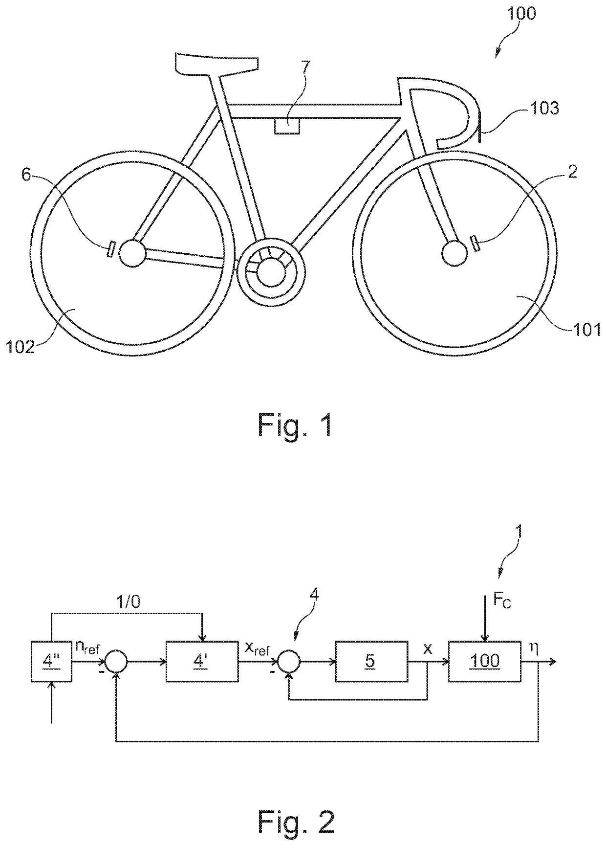
[0013]With reference to FIG. 1, a bicycle is generally indicated by reference 100. The bicycle 100 comprises a front wheel 101 and a rear wheel 102. A brake, actuatable by a lever 103 mounted to the handlebar, for example, is associated to the front wheel 101. The braking system can be of any known type, for example a shoe or disk braking system, commanded by a hydraulic or mechanical system, for example by a cable.

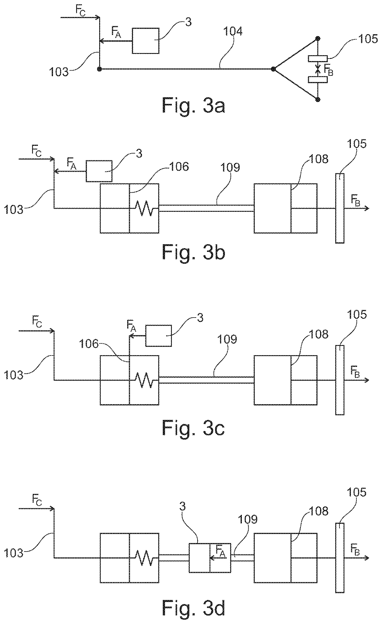
[0014]It is made reference to FIG. 3a-3d, which schematically illustrate possible braking systems of a bicycle.

[0015]FIG. 3a represents a mechanical braking system, wherein the cyclist acts on the lever 103 by applying a force Fc which is transmitted, by means of a mechanical cable 104, to a braking member 105, which is shown as a pair of shoes capable of exerting a braking force FB on the front wheel 101, for example.

[0016]Moreover, on the other hand FIGS. 3b-3d illustrate a hydraulic-type braking system, wherein the cyclist acts on the lever 103 by applying a force Fc w...


PUM


Abstract

The present invention refers to a brake assist system (1) for cyclist on a bicycle (100) including a braking system (101) having a braking member (105) capable of exerting a braking force (FB) on a front wheel (101) of the bicycle (100) by the effect of a force (Fc) applied by the cyclist on a lever (103). The system (1) includes a sensor (2) for measuring the angular speed (ω1) of the front wheel (101) of the bicycle (100); an actuator (3) capable of exerting an actuator force (FA), connectable to said braking system of the bicycle so that the actuator force (FA) opposes the force (Fc) applied by the cyclist on the lever (103), in order to reduce the braking force (FB); and a control module (4) configured for receiving, as an input, the signal representative of the angular speed (ω1) of the front wheel (101) and for determining from this a deceleration (η) of the front wheel (101).

Description

TECHNICAL FIELD OF THE INVENTION[0001]The present invention refers to a brake assist system for a cyclist on a bicycle, particularly a system adapted to help the cyclist to avoid to apply on the front wheel an excessive braking force, which could lock the wheel itself or cause the bicycle to flip over.PRIOR ART[0002]Braking the front wheel of a bicycle is an operation requiring a determined sensibility by the cyclist and, if this operation is not correctly performed, could cause risks and problems. Particularly, an excessively strong braking applied on the front wheel could lock the wheel itself (typically on road surfaces exhibiting a low traction, for example due to the rain), or even could cause the bicycle itself to flip over about the front wheel.[0003]In order to solve this problem, some brake assist systems were provided for braking systems with disk brakes actuated by hydraulic systems which actively intervene on the braking by modulating it.[0004]However, such systems requi...

Claims


Application Information

Patent Timeline
IPC IPC(8): B60T8/32B62L3/02B62L1/06B60T8/58B60T8/74B60T8/76
CPCB62L3/02B60T2230/03B60T8/58B62L3/023B60T8/76B60T8/74B60T2240/00B60T8/3225B62L1/06B60T7/104B60T8/1706B60T2240/06B60T7/085B60T11/165
Inventor CORNO, MATTEOPANZANI, GIULIOSAVARESI, SERGIO MATTEOTODESCHINI, FABIOD'AVICO, LUCAFIORENTI, SIMONECOTA, ALESSIO NICOLÒ
Owner BLUBRAKE SRL
Features
  • Generate Ideas
  • Intellectual Property
  • Life Sciences
  • Materials
  • Tech Scout
  • Unparalleled Data Quality
  • Higher Quality Content
  • 60% Fewer Hallucinations
Learn More