Imaging flow cytometer

Active Publication Date: 2020-02-20
THE UNIV OF TOKYO +1
View PDF0 Cites 2 Cited by
  • Summary
  • Abstract
  • Description
  • Claims
  • Application Information

AI Technical Summary

Benefits of technology

[0019]According to the present invention, it is possible to provide an imaging flow cytometer that generates a three-dimensional image of an observation target at high speed.

Problems solved by technology

However, a method of generating a three-dimensional image of cells under a condition in which cells are observed at high speed using an imaging flow cytometer or the like is not known.

Method used


Image

  • Imaging flow cytometer
  • Imaging flow cytometer
  • Imaging flow cytometer

Examples


first embodiment

Summary of First Embodiment

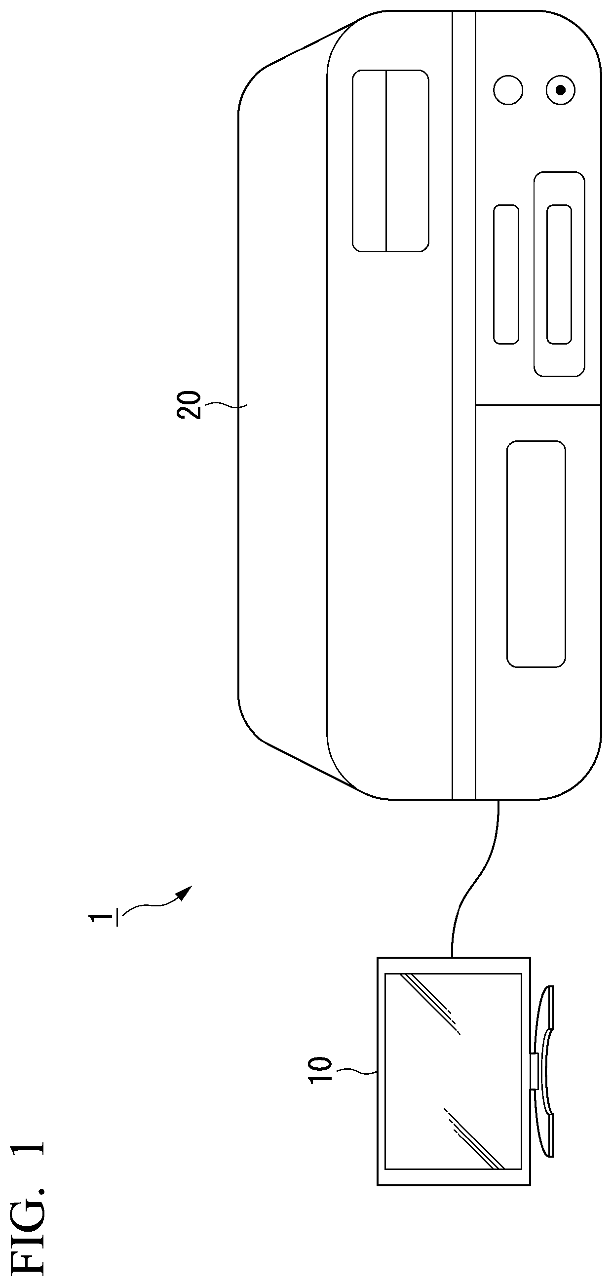
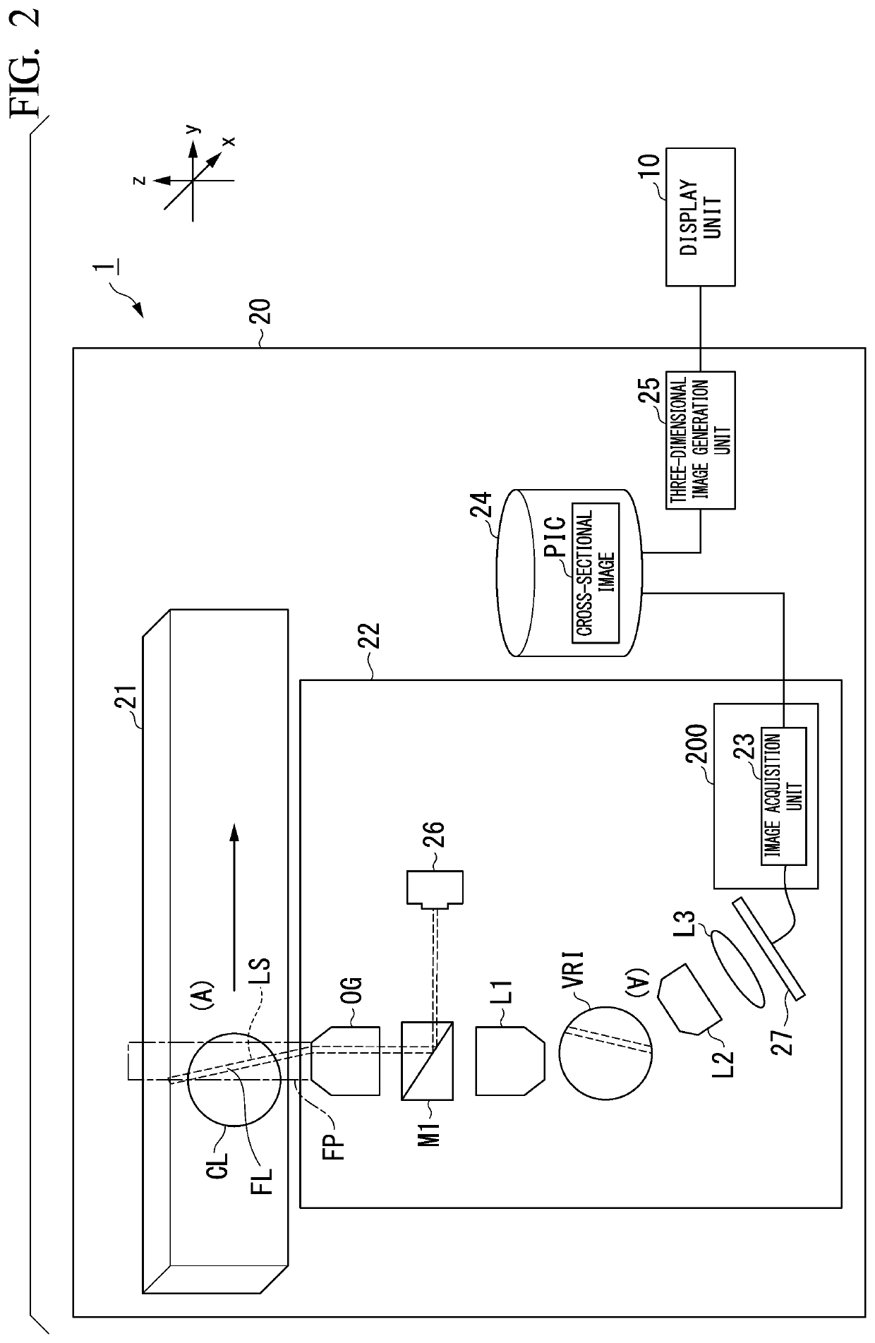
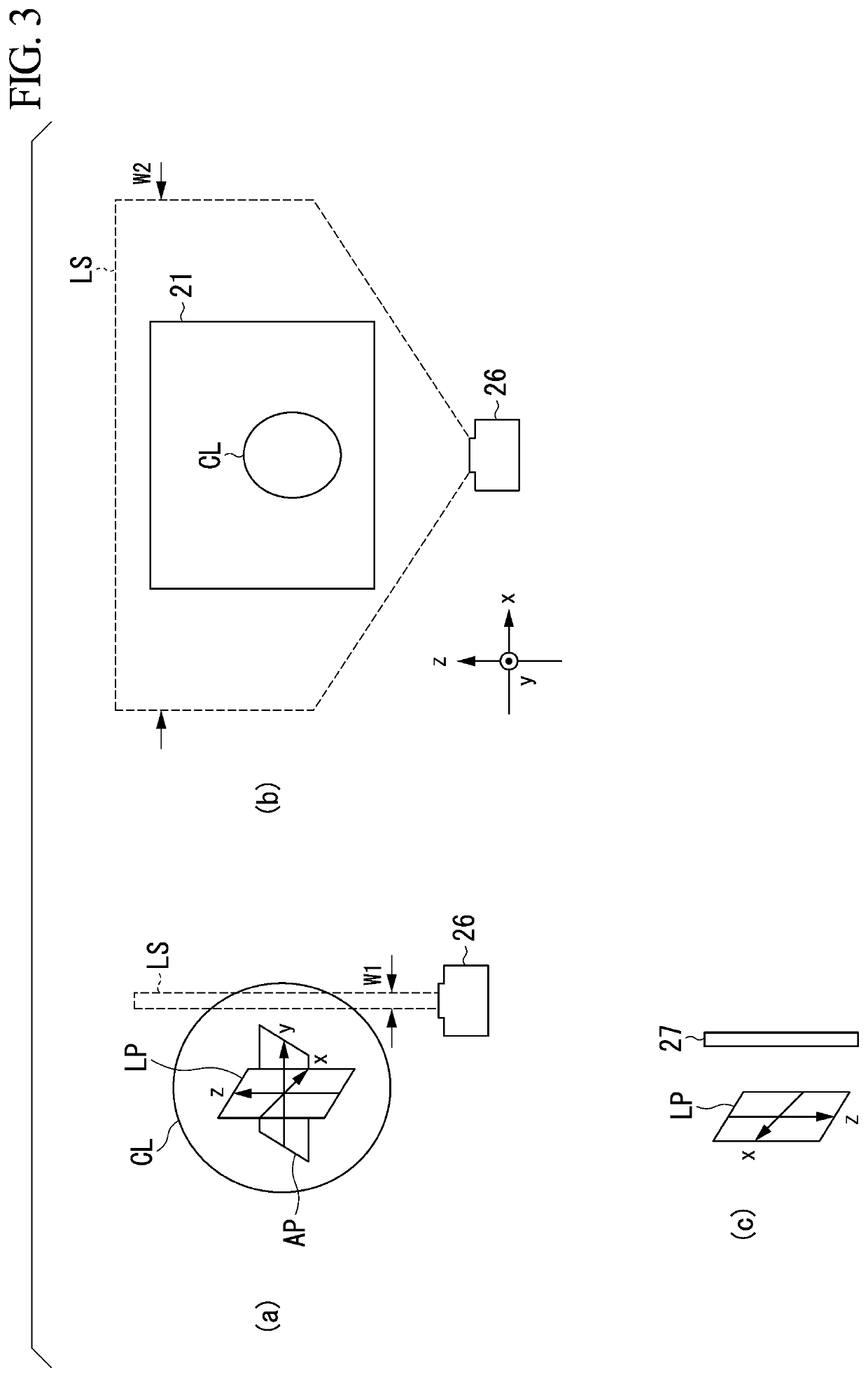
[0078]As described above, the imaging flow cytometer 20 includes the flow channel 21, the imaging unit 22, and the three-dimensional image generation unit 25. The imaging unit 22 images a cross-section of the cell CL flowing through the flow channel 21 as the cross-sectional image PIC. The three-dimensional image generation unit 25 combines the plurality of cross-sectional images PIC captured by the imaging unit 22 to generate a three-dimensional image. Thereby, the imaging flow cytometer 20 can generate a three-dimensional image of the cell CL.

[0079]In addition, the imaging element 27 included in the imaging unit 22 is an imaging element constituted by a sCMOS. The sCMOS can perform imaging at a higher speed than an imaging element constituted by a CMOS or a CCD. The imaging element 27 can capture a large number of images in one second.

[0080]In addition, the sCMOS can generate a high-quality captured image with reduced noise as compared to an imaging elem...

second embodiment

Summary of Second Embodiment

[0118]As described above, the imaging flow cytometer 20a includes the light modulation unit 28, the signal acquisition unit 29, and the image generation unit 30. The signal acquisition unit 29 stores light-intensity information acquired from the imaging element 27a side by side in time-series order. The image generation unit 30 reconfigures the cross-sectional image PIC including a cross-sectional image of the cell CL on the basis of the light-intensity information stored in the signal acquisition unit 29 and arranged in time-series order and optical characteristics of the light modulation unit 28. The reconfigured image is an image having a width in the y-axis direction. Thereby, the imaging flow cytometer 20a can further reduce the number of times of acquisition of a signal from the imaging element 27a compared with in the above-described first embodiment. The imaging flow cytometer 20a can generate a three-dimensional image at higher speed.

[0119]It sho...


PUM

PropertyMeasurementUnit
width W1aaaaaaaaaa
fluorescenceaaaaaaaaaa
fluorescence emissionaaaaaaaaaa

Abstract

An imaging flow cytometer includes at least one flow channel through which an observation target flows, a light source which irradiates the flow channel with sheet-like excitation light, an imaging unit which images a specific cross-section of the observation target by imaging fluorescence from the observation target having passed through a position irradiated with the excitation light, and a three-dimensional image generation unit which generates a three-dimensional image of the observation target as a captured image on the basis of a plurality of captured images obtained by cross-sectional imaging by the imaging unit.

Description

TECHNICAL FIELD[0001]The present invention relates to an imaging flow cytometer.[0002]The application is based on Japanese Patent Application No. 2017-090798 filed on Apr. 28, 2017, the content of which is incorporated herein by reference.BACKGROUND ART[0003]In the related art, a flow cytometry method for fluorescently staining an observation target and evaluating features of the observation target on the basis of the total amount of fluorescence emission, and a flow cytometer using the flow cytometry method are known (for example, Patent Literature 1). In addition, a fluorescence microscope or an imaging cytometer that evaluate particulates such as cells or bacteria serving as an observation target using an image are known.[0004]In addition, an imaging flow cytometer that captures morphological information of particulates at high speed with the same throughput as a flow cytometer is known (for example, Patent Literature 2). In addition, a multiplane optical microscope that irradiat...

Claims


Application Information

Patent Timeline
Patent Type & Authority Applications(United States)
IPC IPC(8): G02B21/00G02B21/18G02B21/04G01N15/14
CPCG01N15/14G02B21/18G02B21/04G02B21/0076G02B21/16G02B21/367G01N2015/1445G01N15/1434G01N15/147G01N15/1475G01N2015/1006G01N15/1429
Inventor UGAWA, MASASHIKAWAMURA, YOKOOTA, SADAO
Owner THE UNIV OF TOKYO
Why Eureka
Try Eureka