Control method for tintable windows

a technology for controlling methods and tintable windows, applied in the field of window controllers, can solve problems such as the inability to realize the full commercial potential of electrochromic windows, the problems of electrochromic windows, and especially the electrochromic devices, and still suffer various problems

Active Publication Date: 2020-02-20
VIEW INC
View PDF0 Cites 14 Cited by
  • Summary
  • Abstract
  • Description
  • Claims
  • Application Information

AI Technical Summary

Benefits of technology

[0016]Another embodiment is a master controller for controlling tint of a tintable window to account for occupant comfort in a building. The tintable window is located between the interior and exterior of the building. The master controller comprises a computer readable medium and a processor in communication with the computer readable medium and in communication with a local window controller for the tintable window. The computer readable medium has a configuration file with a space type associated with the tintable window. The processor is configured to receive the space type from the computer readable medium, determine a tint level for the tintable window based on a penetration depth of direct sunlight through the tintable window into a room and the space type, and send tint instructions over a network to the local window controller to transition tint of the tintable window to the determined tint level.

Problems solved by technology

While electrochromism was discovered in the 1960s, electrochromic devices, and particularly electrochromic windows, still unfortunately suffer various problems and have not begun to realize their full commercial potential despite many recent advances in electrochromic technology, apparatus and related methods of making and / or using electrochromic devices.

Method used


Image

  • Control method for tintable windows
  • Control method for tintable windows
  • Control method for tintable windows

Examples


Embodiment Construction

[0093]In the following description, numerous specific details are set forth in order to provide a thorough understanding of the presented embodiments. The disclosed embodiments may be practiced without some or all of these specific details. In other instances, well-known process operations have not been described in detail to not unnecessarily obscure the disclosed embodiments. While the disclosed embodiments will be described in conjunction with the specific embodiments, it will be understood that it is not intended to limit the disclosed embodiments.

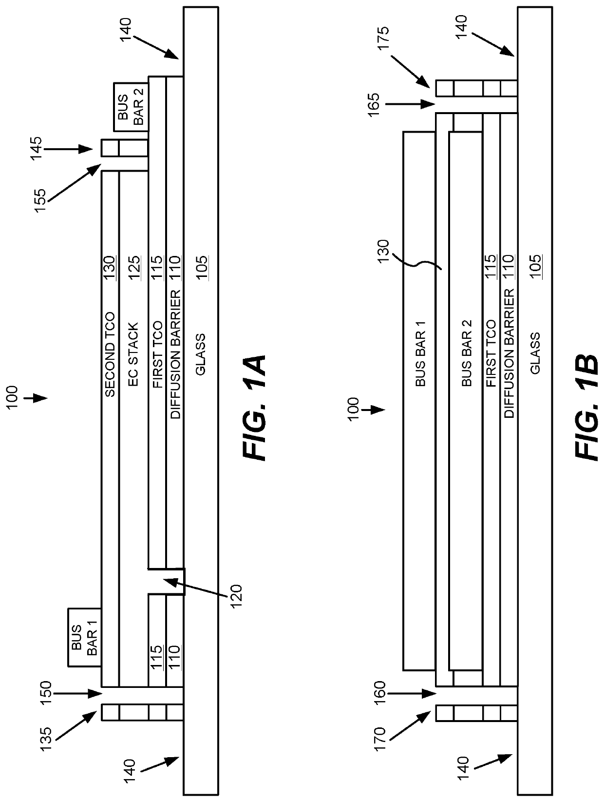
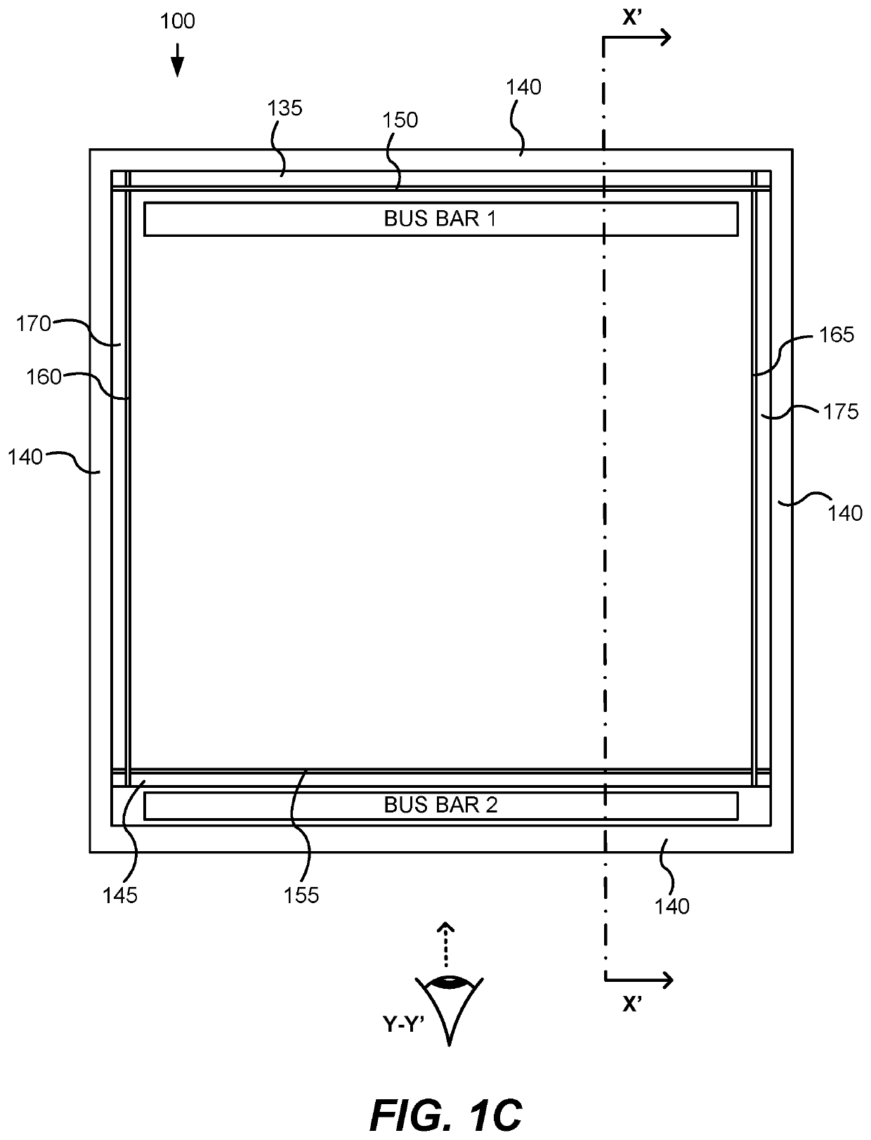
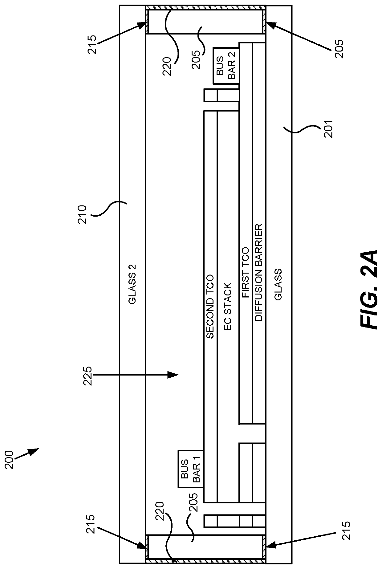
[0094]I. Overview of Electrochromic Devices

[0095]It should be understood that while disclosed embodiments focus on electrochromic windows (also referred to as smart windows), the concepts disclosed herein may apply to other types of tintable windows. For example, a tintable window incorporating a liquid crystal device or a suspended particle device, instead of an electrochromic device could be incorporated in any of the disclosed embod...


PUM

PropertyMeasurementUnit
thickaaaaaaaaaa
thickaaaaaaaaaa
thickaaaaaaaaaa

Abstract

A method of controlling tint of a tintable window to account for occupant comfort in a room of a building. The tintable window is between the interior and exterior of the building. The method predicts a tint level for the tintable window at a future time based on lighting received through the tintable window into the room at the future time and space type in the room. The method also provides instructions over a network to transition tint of the tintable window to the tint level.

Description

PRIORITY DATA[0001]This patent document claims benefit of priority of U.S. Provisional Patent Application No. 62 / 434,826 titled CONTROL METHOD FOR TINTABLE WINDOWS, filed on Dec. 15, 2016 (Attorney Docket No. VIEWP049X2P), which is hereby incorporated by reference in its entirety and for all purposes.[0002]This patent document is also a continuation-in-part of U.S. patent application Ser. No. 15 / 347,677 titled CONTROL METHOD FOR TINTABLE WINDOWS, filed on Nov. 9, 2016 (Attorney Docket No. VIEWP049X1), which is a continuation-in-part of International Patent Application No. PCT / US2015 / 029675 titled CONTROL METHOD FOR TINTABLE WINDOWS, filed on May 7, 2015 (Attorney Docket No. VIEWP049X1WO), which claims benefit of priority of U.S. Provisional Patent Application No. 61 / 991,375 titled CONTROL METHOD FOR TINTABLE WINDOWS, filed on May 9, 2014 (Attorney Docket No. VIEWP049X1P). U.S. patent application Ser. No. 15 / 347,677 is also a continuation-in-part of U.S. patent application Ser. No. 1...

Claims


Application Information

Patent Timeline
Patent Type & Authority Applications(United States)
IPC IPC(8): G02F1/163E06B9/24G05B19/048
CPCG05B2219/2628G05B2219/25011G02F1/163G02F1/15G05B19/048E06B9/24G02F2001/1555G02B5/20E06B2009/2464G05B15/02G05B2219/163G05B2219/2642G05B2219/2653Y02B80/00Y02A30/24
Inventor ZEDLITZ, JASON DAVIDKLAWUHN, ERICH R.BROWN, STEPHEN CLARK
Owner VIEW INC
Why Eureka
Try Eureka