Image capturing device and image capturing module

an optoelectric module and image capturing technology, applied in the field of optoelectric devices and optoelectric modules, can solve the problems of poor image capturing quality and affecting identification, crosstalk problem still cannot be effectively improved by exiting techniques, and the user is not easily perceived by the sensing module, so as to achieve good visual effect and favorable identification capability

Active Publication Date: 2020-02-20
GINGY TECH
View PDF0 Cites 3 Cited by
  • Summary
  • Abstract
  • Description
  • Claims
  • Application Information

AI Technical Summary

Benefits of technology

[0004]The invention provides an image capturing device and an image capturing module featuring a favorable identification capability and good visual effect.
[0007]To sum up, in the image capturing device provided by the exemplary embodiments of the invention, since the light leaking from the clad is absorbed by the light absorbing columns surrounding the fiber, the crosstalk problem is effectively improved. Moreover, the frame body is adhered to the cover plate through the first adhesive layer, the sensing module is adhered to the frame body through the second adhesive layer, and the orthographic projection of the second adhesive layer on the cover plate falls within the orthographic projection of the frame body on the cover plate. Therefore, when viewed from the side of the cover plate, the second adhesive layer is covered by the frame body. By hiding the second adhesive layer under the frame body, it is possible to prevent the second adhesive layer from affecting the visual effect. In addition, since the sensing module is indirectly joined to the cover plate through the second adhesive layer, the frame body and the first adhesive layer, there is no need to provide an adhesive layer between the cover plate and the sensing module not covered by the frame body. With such design, there may be only one light transmission medium (such as air) between the cover plate and the sensing module not covered by the frame body, so the sensing module is not easily perceived by the user. Therefore, the image capturing device features a favorable identifying capability and good visual effect.

Problems solved by technology

In the process of capturing an image by the sensor, the light beam reflected by the fingerprints may easily be transmitted to the sensor in a scattering manner, which may lead to poor image capturing quality and affect the identification result.
Although several techniques are developed to improve the quality of image capturing, the crosstalk problem still can not be effectively improved by the exiting techniques.
With such design, there may be only one light transmission medium (such as air) between the cover plate and the sensing module not covered by the frame body, so the sensing module is not easily perceived by the user.

Method used


Image

  • Image capturing device and image capturing module
  • Image capturing device and image capturing module
  • Image capturing device and image capturing module

Examples


Embodiment Construction

[0016]It should be understood that the foregoing and other detailed descriptions, features, and effects are intended to be described more comprehensively by providing exemplary embodiments accompanied with drawings hereinafter.

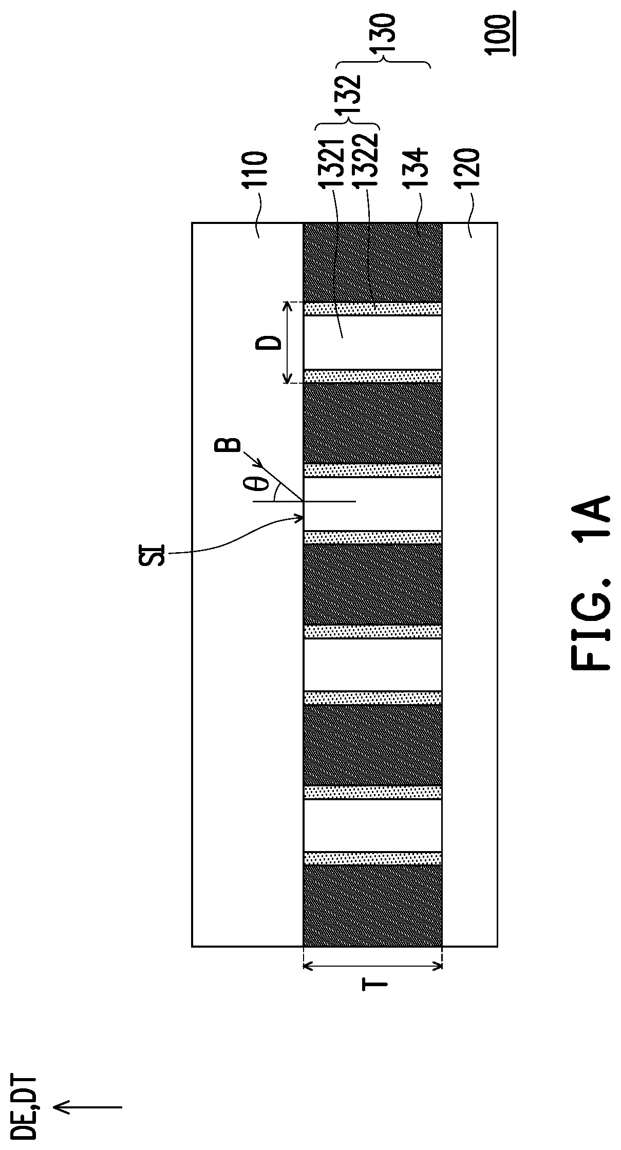
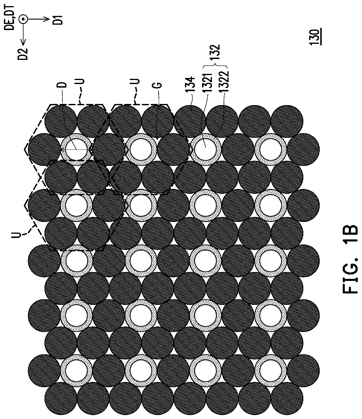
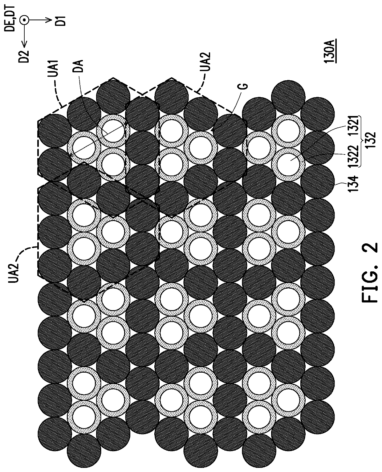
[0017]In the drawings, common characteristics of the methods, structures and / or materials used in specific exemplary embodiments are shown. However, the drawings are not limited to the structures or features of the following exemplary embodiments and the drawings should not be interpreted to define or limit the scopes or the properties of the descriptions in the exemplary embodiments. For instance, the relative thickness and location of each film layer, region, and / or structure may be reduced or enlarged for clarity.

[0018]In the following exemplary embodiments, wording used to indicate directions, such as “up,”“down,”“front,”“back,”“left,” and “right,” merely refers to directions in the accompanying drawings. Therefore, the directional wording is used to illus...


PUM

PropertyMeasurementUnit
included angleaaaaaaaaaa
included angle OCaaaaaaaaaa

Abstract

An image capturing device includes a cover plate, a sensing module, a frame body, a first adhesive layer, and a second adhesive layer is provided. The sensing module includes a sensor and a light collimator. The light collimator is disposed between the cover plate and the sensor. The light collimator includes a plurality of light collimating units. Each of the light collimating units includes at least one fiber and a plurality of light absorbing columns. The light absorbing columns are disposed parallel to the at least one fiber and surround the at least one fiber. A thickness of the light collimator is T. A distance between two light absorbing columns farthest from each other among the light absorbing columns in each of the light collimating units is D. A numerical aperture of the at least one fiber is NA, NA≤0.7, and D≤T×tan[sin−1(NA)].

Description

CROSS-REFERENCE TO RELATED APPLICATION[0001]This application is a continuation-in-part application of and claims the priority benefit of U.S. application Ser. No. 16 / 372,440, filed on Apr. 2, 2019, now allowed, which claims the priority benefit of U.S. provisional application Ser. No. 62 / 693,459, filed on Jul. 3, 2018. This application also claims the priority benefits of U.S. provisional application Ser. No. 62 / 784,755, filed on Dec. 25, 2018, and China application serial no. 201920526854.1, filed on Apr. 18, 2019. The entirety of each of the above-mentioned patent applications is hereby incorporated by reference herein and made a part of this specification.BACKGROUNDTechnical Field[0002]The invention relates to an optoelectric device and an optoelectric module. More particularly, the invention relates to an image capturing device and an image capturing module.Description of Related Art[0003]Types of biometric identification include face, voice, iris, retina, vein, palm print, and ...

Claims


Application Information

Patent Timeline
Patent Type & Authority Applications(United States)
IPC IPC(8): G06K9/00G03B11/00G02B27/30
CPCG03B11/00G02B27/30G06K9/00885G02B3/0056G06V40/1324G06V40/10
Inventor CHUNG, WEI-CHUNWU, JEN-CHIEHLEE, WEN-CHEN
Owner GINGY TECH
Why Eureka
Try Eureka