Automatic positive pressure breathing apparatus

a positive pressure breathing and automatic technology, applied in the field of can solve the problems of affecting the breathing of users, affecting the inability of the automatic positive pressure breathing apparatus to effectively determine the current state of user's breathing, so as to reduce the turbulent flow and effectively determine the user's breathing conditions

Inactive Publication Date: 2020-02-27
ACARE TECH
View PDF0 Cites 1 Cited by
  • Summary
  • Abstract
  • Description
  • Claims
  • Application Information

AI Technical Summary

Benefits of technology

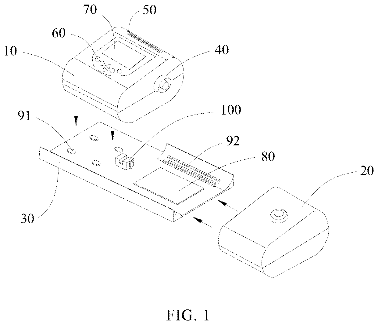
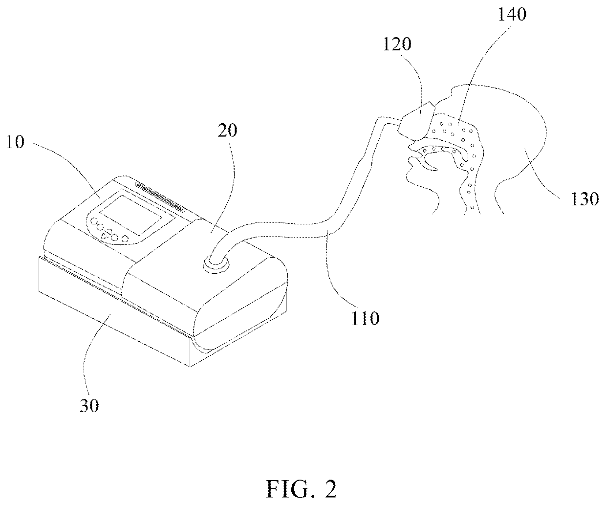
[0006]In view of the aforementioned problems, the present disclosure provides an automatic positive pressure breathing apparatus. When the gas generator generates a first gas, the first gas is imported into the humidification device via the gas flow sensing device. The inside of the automatic positive pressure breathing device includes a radial structure that can effectively reduce the turbulent flow when the first gas is imported into the humidification device. In addition, the gas flow sensing device includes a pressure sensing element that can effectively sense the first gas flow passing through the gas flow sensing device and further have the gas generator adjust the supplied pressure of the first gas. The first gas in the humidification device is imported into the mask device via the breathing tube and is further imported into the user's respiratory tract. The heating device is effectively driven by the control circuit in such a way that the first gas in the humidification device including the water body is attached with vapors. When the automatic positive pressure breathing apparatus is activated, the user generates a second gas and transmits the second gas to the gas generator. The pressure sensing element can be used to effectively determine the user's breathing conditions. Then, the control circuit can be used to adjust the gas pressure supplied by the gas generator and the supplied duration.
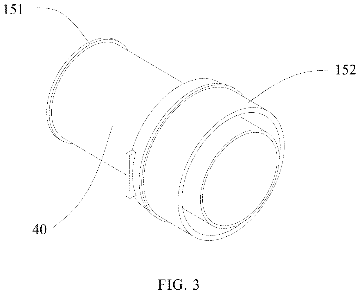
[0017]In sum, the present disclosure, the automatic positive pressure breathing apparatus, has the following advantages:(1) Compared with the conventional automatic positive pressure breathing apparatuses, the automatic positive pressure breathing apparatus includes a gas flow sensing device, and the inside of the gas flow sensing device includes a radial structure. When the gas generator generates the first gas, and the first gas flows to the humidification device via the gaps of the radial structure, the turbulent flow of the first gas can effectively be reduced to further make the first gas steadily transmitted to the upper respiratory tract of the user and reduce the loss of the first gas pressure.(2) Because of the stable gas flow of the first gas generated by the automatic positive pressure breathing apparatus, the gas pressure can effectively be provided for the user to further steadily provide corresponding respiratory treatments according to the user's current breathing conditions. Moreover, through the use of the heating device and the humidification device, the first gas passing through the humidification device can effectively be attached with vapors to prevent the dryness and discomfort of the upper respiratory tract in the user.

Problems solved by technology

In the case where an automatic positive pressure breathing apparatus does not have a stable process of generating gas, the breathable gas passing through the pipeline may not steadily be transmitted to the user's respiratory tract, leading to a loss of gas pressure and increasing turbulent flow.
When the gas pressure provided by the automatic positive pressure breathing apparatus is not the originally set pressure and the gas flow not in a stable condition, the user's breathing may be affected.
In this way, it can be shown that the automatic positive pressure breathing apparatus cannot effectively determine the current state of the user's breathing and perform an effective respiratory treatment by itself.

Method used


Image

  • Automatic positive pressure breathing apparatus
  • Automatic positive pressure breathing apparatus
  • Automatic positive pressure breathing apparatus

Examples


Embodiment Construction

[0024]In the present disclosure, it should be noted that the orientation or positional relationship of the terms “up,”“down,”“in,” and the like is based on that shown in the figures, which is only for ease of describing the present disclosure and simplifying the description. The description does not indicate or imply that the referred devices or elements must have a particular orientation, construction, and operation. Therefore, it should not be understood as a restriction on the present disclosure. In addition, the terms “first,”“second,”“third,” and “fourth” are only used for describing purposes and are not to be construed as indicating or implying relative importance.

[0025]In the present disclosure, it should be noted that the terms “connect,”“embed,”“dispose,”“import,”“transmit,”“sense,” and “attach” should be considered to be general understanding unless there is a specific regulation or restriction. The specific meanings of the aforementioned terms in the present disclosure sh...


PUM


Abstract

An automatic positive pressure breathing apparatus is provided, applicable to connect an upper respiratory tract of a user, which includes a gas generator, a gas flow sensing device, a humidification device, a heating device, a breathing tube, and a mask device. The gas generator includes a signal processing module and a filter. Wherein the signal processing module includes a control circuit and the filter is embedded in the gas generator. The first connecting end of the gas flow sensing device is positioned at one end of the gas flow sensing device and is connected to one side of the gas generator. The second connecting end is positioned at the other end of the gas flow sensing device. The gas flow sensing device includes a first pressure sensing element, a second pressure sensing element, and a radial structure.

Description

CROSS-REFERENCE TO RELATED APPLICATION[0001]This application claims priority from Taiwan Patent Application No. 107211442, filed on Aug. 21, 2018, in the Taiwan Intellectual Property Office, the content of which is hereby incorporated by reference in its entirety for all purposes.FIELD OF THE INVENTION[0002]The present disclosure relates to an automatic positive pressure breathing apparatus, more particularly to a device equipped with functions of sensing gas flow of supplied gas and rectifying currents. The present disclosure may also relate to an automatic positive pressure breathing apparatus which adjusts supplied gas pressure and adjusts supplied gas frequency on the basis of a user's feedback on gas pressure.BACKGROUND OF THE INVENTION[0003]Modern gas flow channels for gas transmission typically only provide conventional pipelines for automatic positive pressure breathing apparatus. In the case where an automatic positive pressure breathing apparatus does not have a stable pro...

Claims


Application Information

Patent Timeline
Patent Type & Authority Applications(United States)
IPC IPC(8): A61M16/00A61M16/10A61M16/12
CPCA61M2016/0027A61M16/024A61M2016/0033A61M2205/3368A61M16/12A61M16/105A61M2205/502A61M2205/52A61M16/0003A61M16/109A61B5/0826A61B5/087A61M16/107A61M16/16A61M2209/086G01F1/34
Inventor CHENG, LIN-TA
Owner ACARE TECH
Why Eureka
Try Eureka