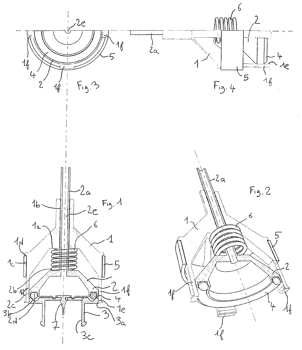
Device for measuring the leakage rate of at least one element of a protective breathing mask

a breathing mask and leakage rate technology, applied in the direction of breathing protection, respiratory device testing, structural/machine measurement, etc., can solve the problems of deterioration of the protection provided to the wearer by his mask, insufficient protection, and long implementation time, so as to eliminate stray leakage and quantitatively assess the inherent performance of the valve

Inactive Publication Date: 2020-02-27
ETAT FR REPRESENTE PAR LE DELEGUE GENERAL POUR LARMEMENT
View PDF0 Cites 0 Cited by
  • Summary
  • Abstract
  • Description
  • Claims
  • Application Information

AI Technical Summary

Benefits of technology

[0024]The measuring means can include a differential pressure gauge making it possible to determine the overpressure ( / vacuum) applied on the communication orifice such as a valve. The evolution of the overpressure ( / vacuum) over time after stopping the overpressure (respectively vacuum) generating means can serve to determine the leakage rate, in addition to or in place of a flow meter.
[0025]The device according to the invention is based on the measurement of the leakage rate through a valve. This leakage rate makes it possible to quantify the inherent performance of the valve. At the same time, this invention can be adapted to the measurement of the performance of civilian mask exhalation valves, other accessories of the mask, etc. In a known manner, the invention must make it possible to test the accessories including a communication orifice directly on the mask, in order to validate its performance in situ. Indeed, placing or removing accessory, for example a valve, on its holder can cause significant damage.
[0026]The idea is therefore to connect directly to the perimeter of the valve, in the case of testing a valve, and to apply a pressure differential representative of the pressure in the mask when a wearer breathes. The leakage rate is thus that of the valve alone, or of the accessory having a tested communication orifice of the mask, while eliminating stray leaks at the mask / head interface.

Problems solved by technology

As a result, if the exhalation valve fails, a significant leak is created and the protection provided to the wearer by his mask is deteriorated, generally significantly.
If the wearer of the mask smells this odorous gas, then the protection is not sufficient.
These tests, which are technically complex and long to implement, are often not able to be carried out without expensive devices.
Furthermore, the mask tests described above generally do not make it possible to discriminate between a leak at the interface between the mask and the face, due for example to a poor mask choice given the morphology of the wearer, or to a poor strap adjustment, on the one hand, and a leak at an accessory of the defective mask, for example the exhalation valve, on the other hand.
However, in such a system, stray leaks may sometimes occur at the mask / inflatable head interface.

Method used


Image

  • Device for measuring the leakage rate of at least one element of a protective breathing mask

Examples


Embodiment Construction

[0037]We will now more particularly describe the structure of a device for measuring the leakage rate according to the invention.

[0038]The device according to this embodiment includes:[0039]an air intake in overpressure, typically in the case of a test bench, or then an integrated overpressure generating system, for example via a small pump, in the case of a portable variant;[0040]a valve system controllable to allow or not allow an air flow to pass, depending on a setpoint;[0041]a flow meter to measure the overall volume that is injected into the volume confined above the valve to maintain a constant overpressure;[0042]a connector making it possible to have the air arrive above the valve, outside the mask, tightly, in situ on the mask;[0043]a differential pressure gauge making it possible to determine the overpressure applied on the valve that will be used as means for monitoring the overpressure generating means;[0044]a control-command electronic board, which, in this embodiment, ...


PUM


Abstract

Disclosed is a device for measuring the leakage rate of at least part of a protective breathing mask, the mask having at least one communication orifice between the interior, by way of an inlet, and the exterior, by way of an outlet. The communication orifice has an open position, in which a fluid can pass through the orifice between the inlet and outlet, and a closed position, preventing fluid passage through the orifice. The measurement device includes: a mechanism generating a pressure differential between the interior and exterior of the mask; a monitoring unit for the pressure generator; a unit measuring leakage of the communication orifice, in the closed position, at the level of the inlet and outlet, respectively; and a unit by which the pressure generator is fixed near the communication orifice.

Description

BACKGROUND OF THE INVENTIONField of the Invention[0001]The present invention relates to the technical field of devices for measuring the leakage rate of at least one element of a protective breathing mask, the protective breathing mask having at least one communication orifice between the interior of the mask, by way of an inlet, and the exterior of the mask, by way of an outlet, the communication orifice having an open position, in which a fluid can pass through the orifice between the inlet and the outlet, and a closed position, in which a fluid cannot pass through the orifice.Description of the Related Art[0002]A protective breathing mask, whether it involves a half-mask or a full mask, makes it possible to protect the wearer from particles (aerosols) or gas by filtering the air intended for the wearer of the mask through a filtration device. Except for the simplest masks, the exhalation of the wearer is done through an exhalation valve. Thus, the exhaled air does not pass back t...

Claims


Application Information

Patent Timeline
Patent Type & Authority Applications(United States)
IPC IPC(8): A62B27/00G01M3/32
CPCG01M3/3218A62B18/10A62B27/00G01M3/3254G01M3/3209G01M3/3263G01M3/2876
Inventor CHANDESRIS, BENOÎT
Owner ETAT FR REPRESENTE PAR LE DELEGUE GENERAL POUR LARMEMENT
Why Eureka
Try Eureka