Supercharge Your Innovation With Domain-Expert AI Agents!

Bidirectional Split Flow Fluid Phase Separation System

a fluid phase separation and split flow technology, applied in the field of phase separation systems, can solve the problem of processing functionality being overrun by speed

Inactive Publication Date: 2020-02-27
HODGE RONALD ALLEN
View PDF0 Cites 0 Cited by
  • Summary
  • Abstract
  • Description
  • Claims
  • Application Information

AI Technical Summary

Benefits of technology

The patent text explains that using a bidirectional flow separation chamber can double the volumetric flow while keeping the same velocity compared to a unidirectional flow separation chamber. This means that the cross-sectional area required can be reduced by half, leading to cost reductions in the separation chamber construction. In summary, the patent text highlights the benefits of using a bidirectional flow separation chamber to optimize separation efficiency while reducing costs.

Problems solved by technology

Typically, separation chambers can be longer to allow for needed drop-out time, but velocity has an upper limit for processing functionality, so the available cross-sectional area typically drives the design of fluid phase separation chambers.

Method used


Image

  • Bidirectional Split Flow Fluid Phase Separation System
  • Bidirectional Split Flow Fluid Phase Separation System
  • Bidirectional Split Flow Fluid Phase Separation System

Examples


Embodiment Construction

[0019]All illustrations of the drawings are for the purpose of describing selected versions of the present invention and are not intended to limit the scope of the present invention.

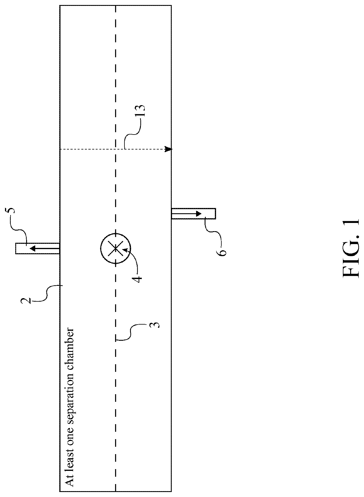
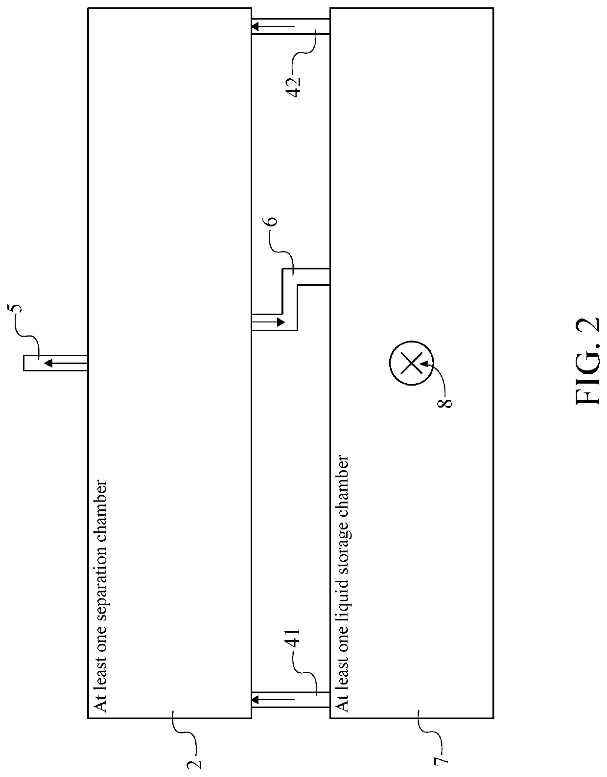
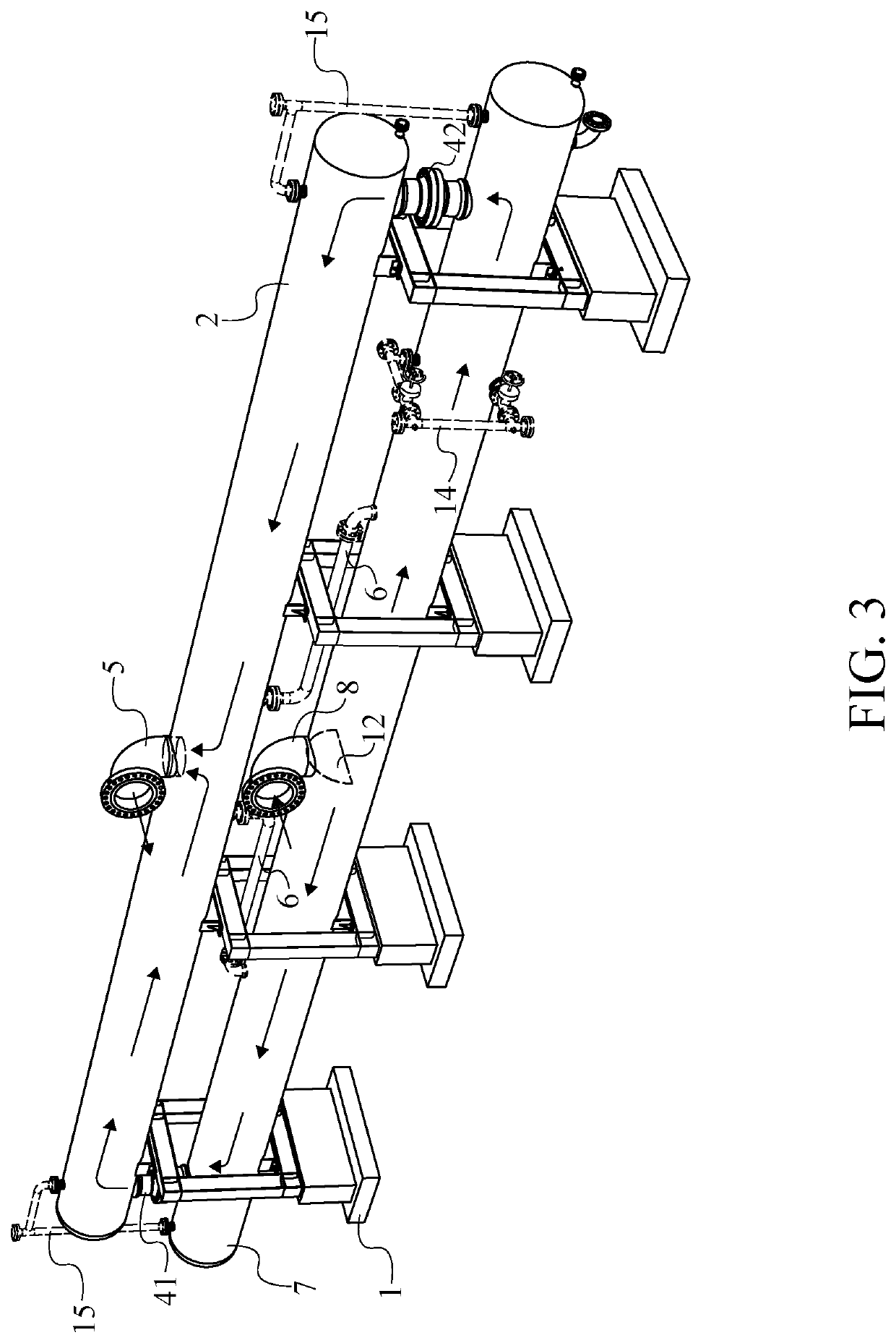
[0020]In reference to FIGS. 1 through 6, the present invention is a bidirectional split flow fluid phase separation system that improves the gravity settling method. The present invention comprises a structural base 1, at least one separation chamber 2, at least one multi-phase flow inlet 4, at least one gas flow outlet 5, and at least one liquid-drop outlet 6. The structural base 1 is used to support the at least one separation chamber 2. The at least one separation chamber 2 is used to separate a multi-phase flow into a gas phase flow and a liquid phase flow. The at least one multi-phase flow inlet 4 is used to receive the multi-phase flow. The at least one gas flow outlet 5 is used to output the separated gas phase flow. The at least one liquid-drop outlet 6 is used to output the separated liquid phas...


PUM

PropertyMeasurementUnit
phaseaaaaaaaaaa
momentumaaaaaaaaaa
densitiesaaaaaaaaaa

Abstract

A bidirectional split flow fluid phase separation system is used to improve the gravity settling method. The bidirectional split flow fluid phase separation system comprises a structural base, at least one separation chamber, at least one multi-phase flow inlet, at least one gas flow outlet, and at least one liquid-drop outlet. The structural base is used to support the at least one separation chamber. The at least one separation chamber is used to separate a multi-phase flow into a gas phase flow and a liquid phase flow. The at least one multi-phase flow inlet is used to receive the multi-phase flow. The at least one gas flow outlet is used to output the separated gas phase flow. The at least one liquid-drop outlet is used to output the separated liquid phase flow.

Description

[0001]The current application claims a priority to the U.S. Provisional Patent application Ser. No. 62 / 720,830 filed on Aug. 21, 2018.FIELD OF THE INVENTION[0002]The present invention generally relates to natural gas and oil processing systems and methods. More specifically, the present invention relates to phase separation systems in natural gas and oil processing. The present invention aims to improve on the conventional gravity settling separation method.BACKGROUND OF THE INVENTION[0003]Separation equipment in natural gas and oil processing equipment is used to separate gas, liquids, solids, or a combination of these phases. Separation of these phases is typically done by individual separation methods or a combination of various separation methods. The traditional separation methods are momentum, gravity settling, and coalescing. For any of these methods to work, the fluid phase must be immiscible and have different densities.[0004]The gravity settling method typically takes plac...

Claims


Application Information

Patent Timeline
Patent Type & Authority Applications(United States)
IPC IPC(8): B01D45/02
CPCB01D45/02B01D45/04E21B43/34
Inventor HODGE, RONALD ALLEN
Owner HODGE RONALD ALLEN
Features
  • R&D
  • Intellectual Property
  • Life Sciences
  • Materials
  • Tech Scout
  • Unparalleled Data Quality
  • Higher Quality Content
  • 60% Fewer Hallucinations
Learn More