Supercharge Your Innovation With Domain-Expert AI Agents!

Side channel blower, especially for a vehicle heater

a technology for vehicle heaters and blowers, which is applied in the direction of positive displacement liquid engines, piston pumps, liquid fuel engines, etc., can solve the problems of comparatively high noise emission and superproportional increase in and achieve the effect of minimizing the noise emitted by blowers

Active Publication Date: 2016-06-09
EBERSPACHER CLIMATE CONTROL SYST GMBH
View PDF23 Cites 1 Cited by
  • Summary
  • Abstract
  • Description
  • Claims
  • Application Information

AI Technical Summary

Benefits of technology

The present invention provides a side channel blower for a vehicle heater that operates economically and with low noise levels even at a high required conveying output. This is achieved by operating two delivery wheels in parallel, each delivering a defined quantity of medium to be delivered. This design reduces the power drain and noise emission compared to a single delivery wheel. The motor shaft is designed to easily couple with the delivery wheels, and a compact design with good utilization of space is achieved by orienting the two axial sides away from each other. A delivering medium outlet space is formed in the blower housing to discharge the delivering medium as a uniform flow. Additionally, the patent proposes that the two delivery channels or blower wheels are arranged with an angular offset in relation to each other to minimize the noises emitted by the blower.

Problems solved by technology

Since both the power drain, i.e., for example, the electric power consumption of the blower motor, and the level of the noises being emitted increase superproportionally with increasing speed of rotation of the blower motor and hence of the delivery wheel, prior-art side channel blowers operate, especially when a vehicle heater is to be operated with a high heat output, not only comparatively uneconomically, but also with a comparatively high noise emission.

Method used


Image

  • Side channel blower, especially for a vehicle heater
  • Side channel blower, especially for a vehicle heater
  • Side channel blower, especially for a vehicle heater

Examples


Embodiment Construction

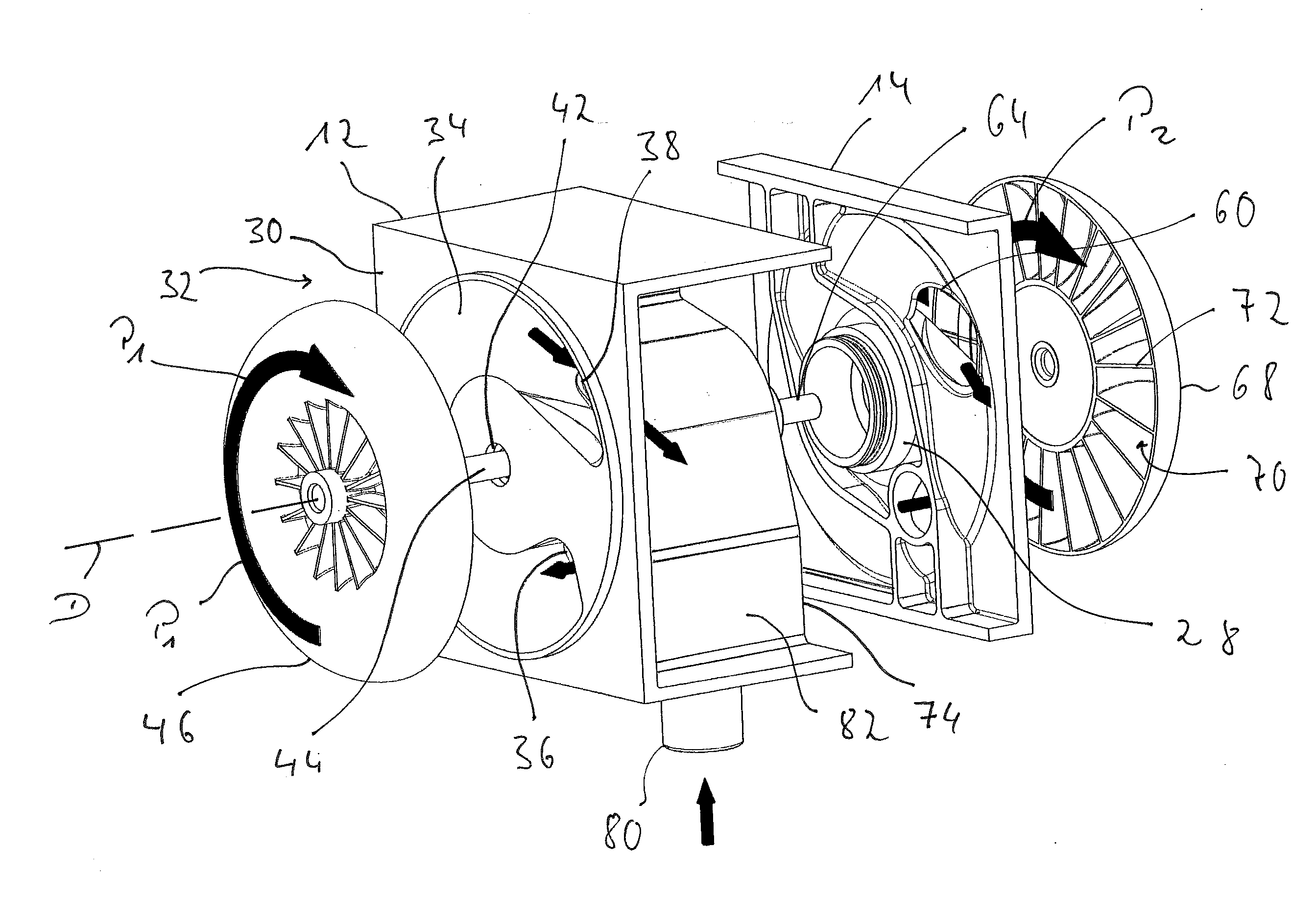
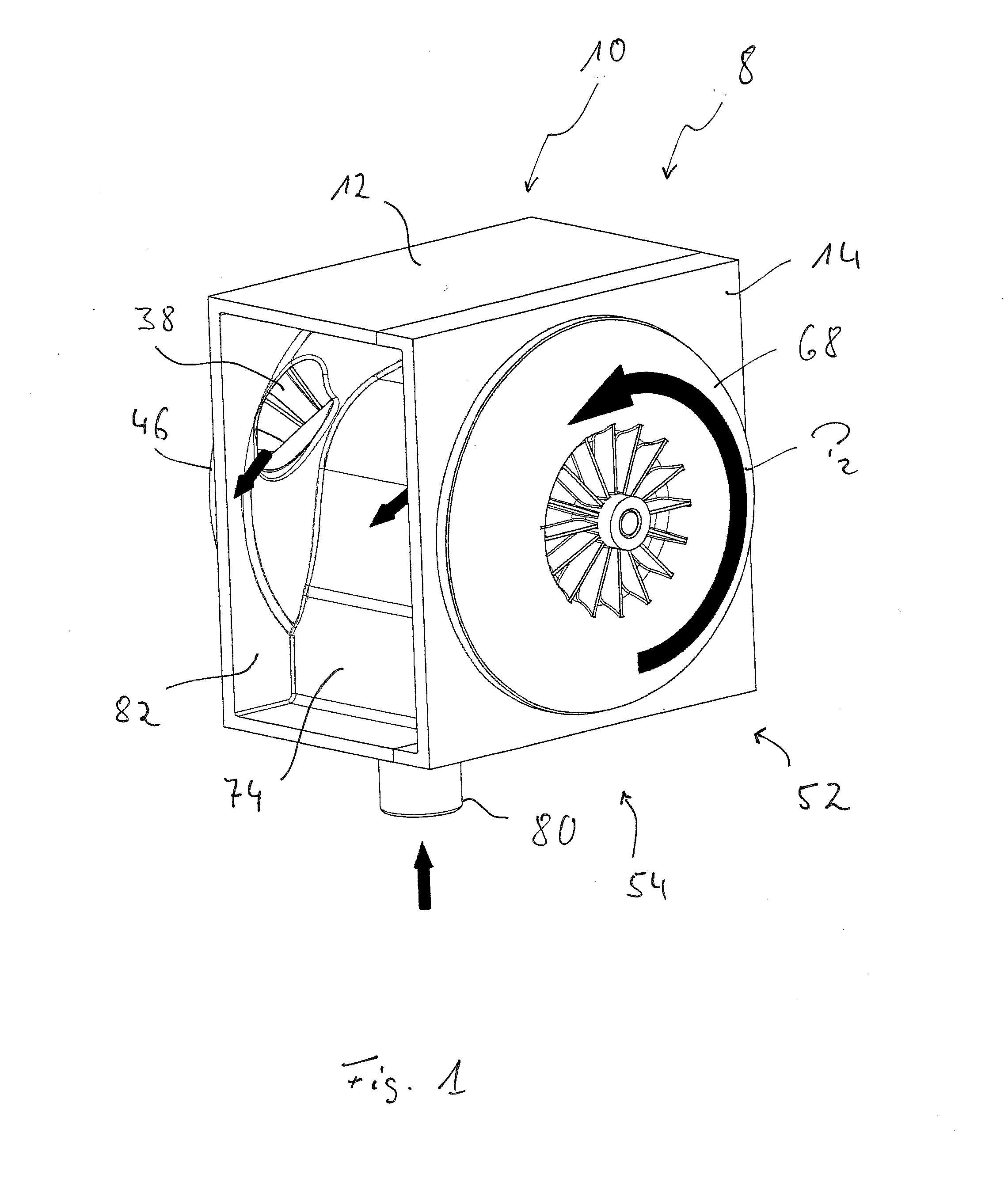
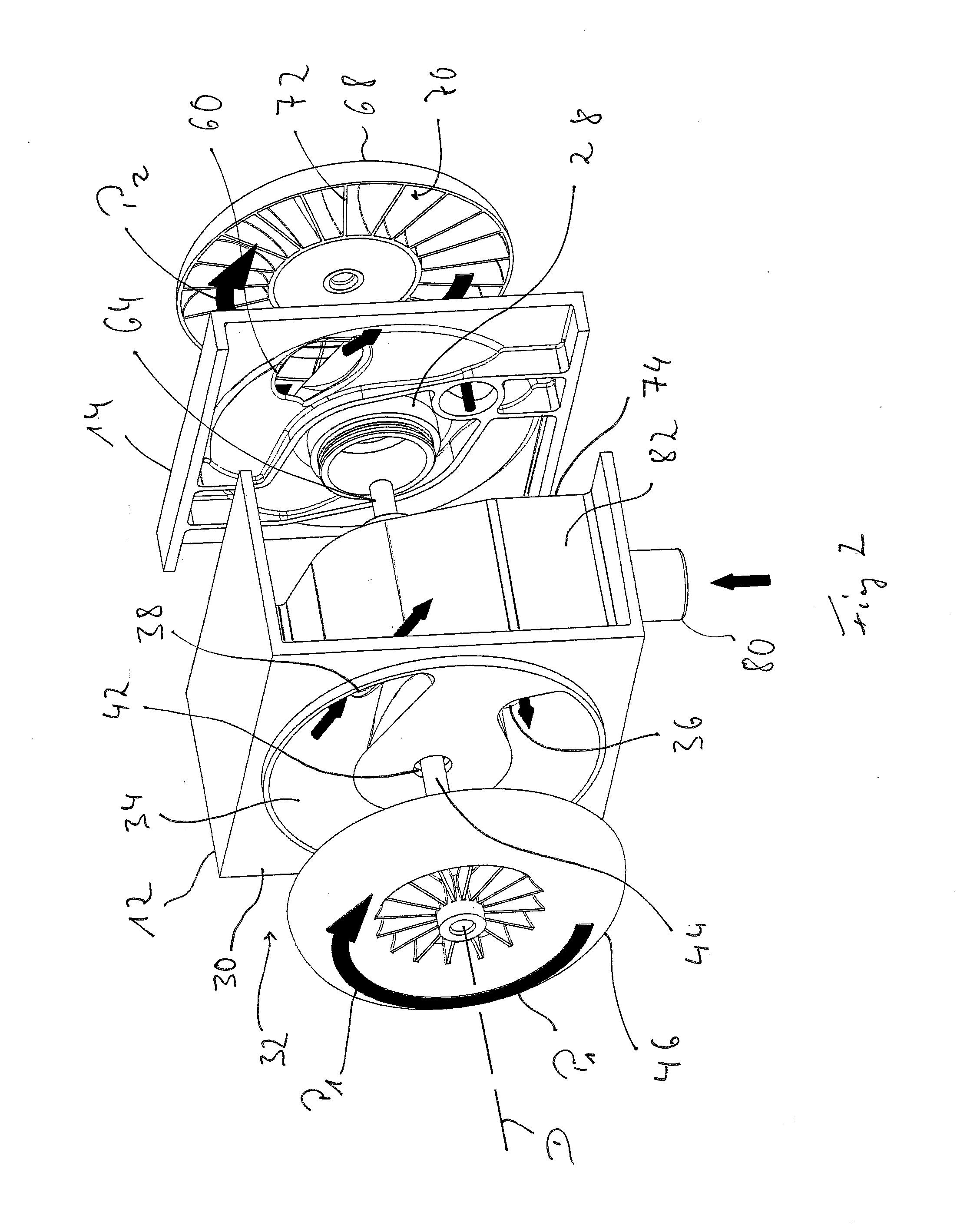
[0030]Referring to the drawings, a side channel blower is generally designated by 8 in FIG. 1. The side channel blower 8, which can be used, for example, to deliver combustion air to a fuel-operated vehicle heater, comprises a blower housing 10, which is provided with a first housing part 12 and a second housing part 14 in the example being shown. A blower motor, which can be energized electrically, is provided with a stator 18 and a rotor 22 coupled with a motor shaft 20 and is generally designated by 16, is provided in the blower housing 10. At the first housing part 12 as well as at the second housing part 14, a blower motor housing area 24 essentially accommodating the blower motor 16 comprises essentially regular cylindrical walls 26, 28 each, which are arranged essentially concentrically to an axis of rotation D of the blower motor 16 and together surround a motor installation volume of the blower housing 10 in the assembled state.

[0031]A first blower housing area 30 is provid...


PUM


Abstract

A side channel blower includes a housing (10) a motor (16) with a motor shaft that rotates about a motor axis. A first blower housing area (30) has a first delivery channel (34) with an inlet (36) and outlet (38) and is open towards a first axial side (32) and surrounds the motor axis. A first delivery wheel (46) covers the first delivery channel (34) and is carried at a first end area (44) of a motor shaft (20). A second blower housing area (52) has a second delivery channel (56) with an inlet (58) and with an outlet (60) and is open towards a second axial side (54) and surrounds the motor axis. A second delivery wheel (68) is located opposite the second axial side (54) and covers the second delivery channel (56) and is carried at a second end area (64) of the motor shaft (20).

Description

CROSS REFERENCE TO RELATED APPLICATIONS[0001]This application claims the benefit of priority under 35 U.S.C. §119 of German Patent Application 10 2014 224 954.6 filed Dec. 5, 2014, the entire contents of which are incorporated herein by reference.FIELD OF THE INVENTION[0002]The present invention pertains to a side channel blower, which can be used, for example, in a vehicle heater in order to deliver the combustion air necessary for the combustion with fuel from the area surrounding the vehicle heater into a combustion chamber.BACKGROUND OF THE INVENTION[0003]Such a side channel blower comprises a blower motor with a motor shaft, at the end area of which a delivery wheel is carried. The delivery wheel covers an axially open delivery channel surrounding the motor shaft and the axis of rotation thereof in a ring-shaped manner. The air to be delivered can enter the delivery channel in a delivering medium inlet and can exit the delivery channel in a delivering medium outlet provided, in...

Claims


Application Information

Patent Timeline
Patent Type & Authority Applications(United States)
IPC IPC(8): F04D25/12F04D25/06F04D29/66F04D29/28F04D29/42F04D17/08F04D29/053
CPCF04D25/12F04D17/08F04D25/06F04D29/663F04D29/281F04D29/4206F04D29/053F04D23/008F04D25/166
Inventor HUMBURG, MICHAELEPPLER, HERMANN
Owner EBERSPACHER CLIMATE CONTROL SYST GMBH
Features
  • R&D
  • Intellectual Property
  • Life Sciences
  • Materials
  • Tech Scout
  • Unparalleled Data Quality
  • Higher Quality Content
  • 60% Fewer Hallucinations
Learn More