Supercharge Your Innovation With Domain-Expert AI Agents!

Construction machine and method for controlling a construction machine

a construction machine and construction technology, applied in the direction of machines/engines, servomotors, ways, etc., can solve the problem that the pump cannot provide the associated hydraulic components with a sufficient volume flow

Active Publication Date: 2022-10-11
WIRTGEN GMBH
View PDF44 Cites 1 Cited by
  • Summary
  • Abstract
  • Description
  • Claims
  • Application Information

AI Technical Summary

Benefits of technology

The invention aims to improve the function of hydraulic components in construction machines with minimal effort. This is achieved by making available excess hydraulic fluid from one hydraulic component to another under certain operating conditions. The excess fluid can be supplied through a check valve to ensure rapid operation of the hydraulic component. The invention also provides a hydraulic control device that can be controlled based on the differential pressure, and a method to quickly extend the piston-cylinder arrangements of the machine frame when relocating the machine. The technical effects of the invention include improved dynamic behavior of hydraulic components, reduced energy consumption, and improved efficiency of construction machines.

Problems solved by technology

In practice, however, it has been shown that individual hydraulic pumps cannot provide the associated hydraulic components with a sufficient volume flow of hydraulic fluid in a short time under certain operating conditions.

Method used


Image

  • Construction machine and method for controlling a construction machine
  • Construction machine and method for controlling a construction machine
  • Construction machine and method for controlling a construction machine

Examples


Embodiment Construction

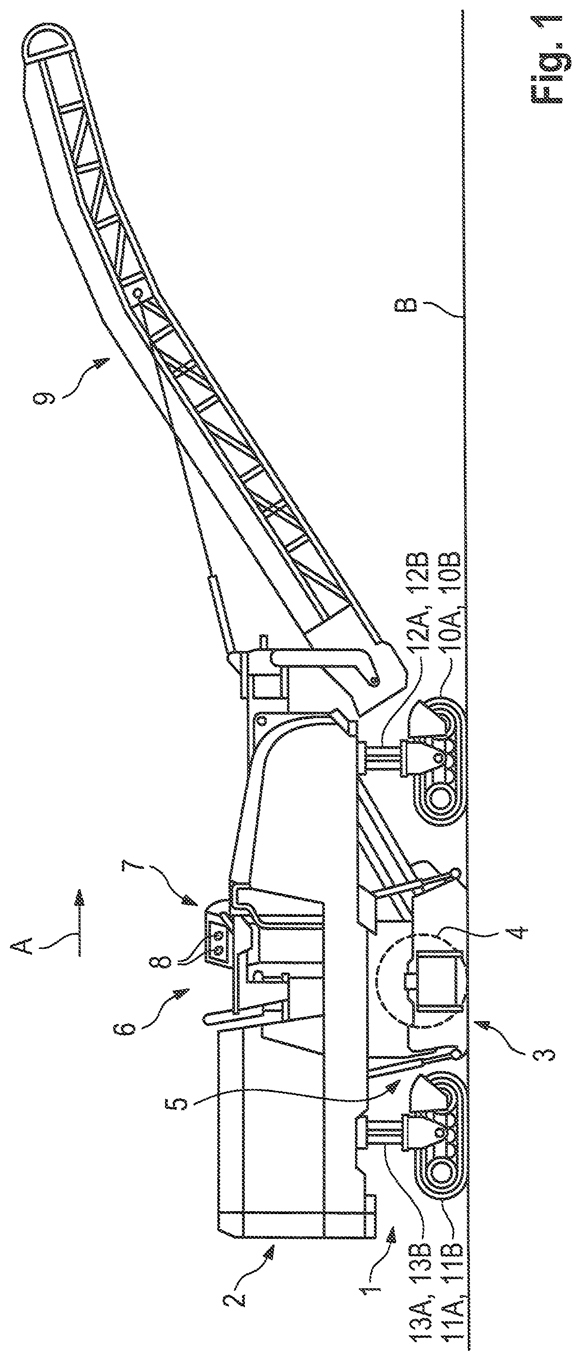
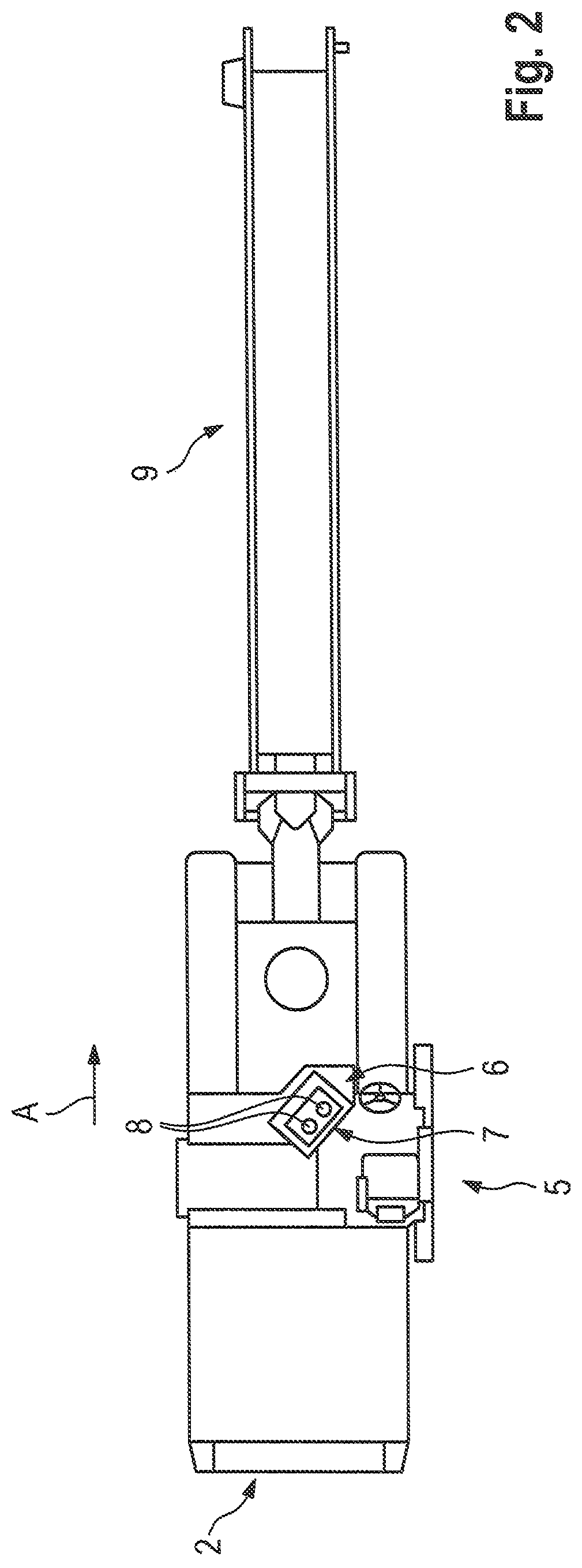
[0031]FIGS. 1 and 2 show inside and top view, as an example of a construction machine, a self-propelled road milling machine for milling road surfaces, which is a front loading road milling machine. The construction machine has a machine frame 2 supported by a chassis 1, on which work equipment 3 is arranged, with which the work required for the construction measure can be carried out. The work equipment 3 has a milling drum 4, which is only schematically shown in FIG. 1 and is arranged in a milling drum housing 5. Above the milling drum housing 5, there is the operator station 6 on the machine frame having an operating panel 7 for the machine operator. The operating panel 7 has a plurality of operating elements 8 which the machine operator can operate. The milled material is removed by a conveyor 9 which is pivotally arranged on the front of the machine frame 2.

[0032]The construction machine has in the working direction A front left running gear 10A and a front right running gear 1...


PUM


Abstract

The invention relates to a construction machine, road milling machine, stabiliser, recycler, surface miner, and a to method for controlling a construction machine. The construction machine has a machine frame 2 supported by a chassis 1 and a plurality of hydraulic systems 15, 16, each of which has at least one hydraulic component 18, 22, at least one hydraulic pump 17, 21 for conveying hydraulic fluid for the at least one hydraulic component and at least one hydraulic line 28, 31 for transporting the hydraulic fluid from the at least one hydraulic pump to the at least one hydraulic component. The drive device of the construction machine comprises at least one internal combustion engine 24. A power transmission device 44 is provided for transmitting at least part of the drive power from the internal combustion engine 24 to the hydraulic pumps 17, 21. The construction machine according to the invention is characterised by a hydraulic control device 26, which is assigned to two hydraulic systems 15, 16 of the plurality of hydraulic systems. The hydraulic control device 16 is designed such that, in a special operating mode, at least part of the hydraulic fluid delivered by the hydraulic pump 17 of the one hydraulic system 15 is supplied to the other hydraulic system 16.

Description

BACKGROUND OF THE INVENTION1. Field of the Invention[0001]The invention relates to a construction machine, in particular a road milling machine, stabiliser, recycler or surface miner, and to a method for controlling a construction machine having a machine frame which is supported by a chassis.2. Description of the Prior Art[0002]The known self-propelled construction machines generally have a machine frame which is supported by a chassis having a plurality of running gears which can be tracks or wheels. Self-propelled construction machines are known which have working equipment for working the ground, for example for removing damaged road layers (road milling machine), for preparing the ground for road construction or reprocessing existing road surfaces (stabilisers, recyclers) or for mining mineral resources (surface miner). Lifting devices are generally assigned to the individual running gears of the construction machine, which lifting devices comprise piston arrangements / cylinder ...

Claims


Application Information

Patent Timeline
Patent Type & Authority Patents(United States)
IPC IPC(8): B60G21/00B60G17/018E01C23/088F02B63/06F15B13/044
CPCB60G17/018E01C23/088F02B63/06F15B13/044B60G2204/201B60G2500/302F15B11/17F15B13/06E02F9/2264E02F9/2267F01P5/04F15B2211/20576F15B2211/71F15B2211/20523F15B2211/4053F15B2211/7142F15B2211/781E01C19/48E01C19/23
Inventor BURKHARD, FRANK
Owner WIRTGEN GMBH
Features
  • R&D
  • Intellectual Property
  • Life Sciences
  • Materials
  • Tech Scout
  • Unparalleled Data Quality
  • Higher Quality Content
  • 60% Fewer Hallucinations
Learn More