Aircraft landing gear arrangement

a landing gear and aircraft technology, applied in the field of aircraft landing gear arrangement, can solve the problems of large void, noise and drag, seals will naturally deflate, etc., and achieve the effects of improving fuel efficiency, reducing drag and noise, and more aerodynamic profil

Active Publication Date: 2020-02-27
AIRBUS OPERATIONS LTD
View PDF0 Cites 0 Cited by
  • Summary
  • Abstract
  • Description
  • Claims
  • Application Information

AI Technical Summary

Benefits of technology

[0014]Having the airbag substantially close off the landing gear bay, when the landing gear is extended, has the advantage of the landing gear arrangement, and therefore the aircraft with the landing gear arrangement, having a more aerodynamic profile when the landing gear is extended. This means the drag and noise are lower. This means the fuel efficiency, especially important on take-off, is improved and also the noise levels, especially important when landing, are lowered.
[0040]The invention, according to the second aspect, is different to the “door-less” arrangement where the landing gear bay is an open void when the landing gear is extended (with only the small seals acting to cover a small outside circumference of the void). The present invention, according to the second aspect, also has the advantage the landing gear bay does not have to be designed to correspond so closely to the wheel size. Hence, the present invention, according to the second aspect, may be used for a bogie landing gear. The invention, according to the second aspect, is also different to the GB 2344325 arrangement where the emergency airbag is not concerned with, or disclosed as, significantly closing off the landing gear bay. In addition, the present invention, according to the second aspect, provides an external surface of the airbag that acts as an aerodynamic fairing, in a similar way to the external surface of the convention, rigid landing gear doors. This effectively provides a single aerodynamic surface (including both the aircraft body external surface and the airbag external surface), hence, making the arrangement more aerodynamic and helping to minimising noise and drag.

Problems solved by technology

Similarly, the seals will naturally deflate when the landing gear is brought to a lower altitude, because of the higher ambient pressure.
However, this arrangement has the disadvantage that when the landing gear is extended, there is a large void (at least the size of a wheel).
This void causes noise and drag issues.
In particular, it causes noise issues when the aircraft is landing or taking off which can be disruptive to residents near airports and may conflict with nose regulations.
In addition, the arrangement has the disadvantage that the aperture of the landing gear bay has to be precisely shaped around the wheel.
Therefore, such an arrangement cannot be used for bogie landing gear arrangements, where the landing gear wheels are mounted either end of an axle, the axle being transverse to the landing gear leg.
This creates a non-aerodynamic surface and is very disadvantageous from a noise and drag point of view.
Hence, this arrangement could not be used for aerodynamic purposes.
Of course, this means that this arrangement could not be used in a routine manner.

Method used


Image

  • Aircraft landing gear arrangement
  • Aircraft landing gear arrangement
  • Aircraft landing gear arrangement

Examples


Embodiment Construction

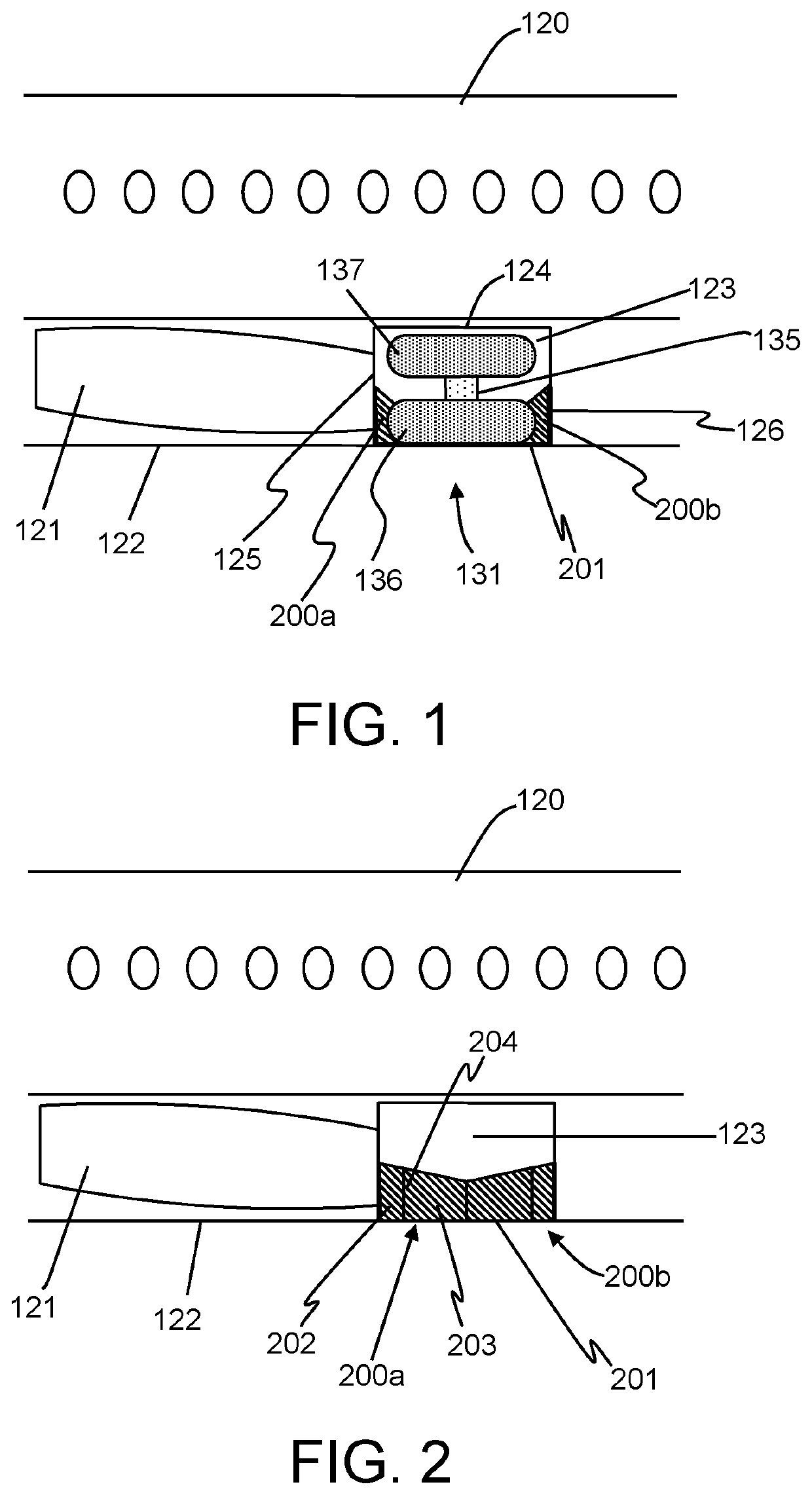
[0057]FIG. 1 shows a side cross-sectional view of a central section of an aircraft 100 including a landing gear arrangement according to a first embodiment of the invention, the landing gear being in a retracted, or stowed, configuration. The aircraft 100 comprises a fuselage 120. The fuselage contains the central wing box 121 and has an external lower surface 122.

[0058]Provided in the fuselage is a landing gear bay 123. The bay 123 is defined by a roof 124 and side walls 125, 126. An open face of the landing gear bay 123 faces downwards, and through this face, a landing gear 131 (a right main landing gear) can deploy. As shown in FIG. 1, the landing gear 131 is stowed within the bay 123. The open face of the bay 123 has an area of approximately 10 square metres.

[0059]The landing gear 131 has been pivoted inwards (during stowing) so as to be on its side. Hence, as shown, there is an upper wheel 137 (that becomes an inner wheel when deployed) and a lower wheel 136 (that becomes an ou...


PUM


Abstract

An aircraft landing gear arrangement with an airbag attached inside a landing gear bay is disclosed. The airbag has a deflated configuration and a first inflated configuration, wherein, when the landing gear is in the extended position and when the airbag is in the first inflated configuration, the airbag closes off the landing gear bay. The airbag may substantially close off the landing gear bay. The airbag may comprise an external surface, wherein the external surface of the airbag closes off at least a significant proportion of the landing gear bay and lies substantially flush with an external surface of the aircraft body. An aircraft, methods of operating a landing gear arrangement, and methods of operating an aircraft are disclosed.

Description

BACKGROUND OF THE INVENTION[0001]The present disclosure relates to an aircraft landing gear arrangement.[0002]The present invention concerns aircraft landing gear arrangements. More particularly, but not exclusively, this invention concerns an aircraft landing gear arrangement comprising a landing gear bay, a landing gear comprising a landing gear leg and a landing gear wheel mounted on the landing gear leg, the landing gear being moveable between a retracted position where the landing gear leg and landing gear wheel are both retracted within the landing gear bay, and an extended position where the landing gear leg and landing gear wheel are both extended out of the landing gear bay such that the landing gear is arranged for landing, and an airbag attached inside the landing gear bay, the airbag having a deflated configuration and a first inflated configuration.[0003]The invention also concerns an aircraft, methods of operating a landing gear arrangement, and methods of operating an...

Claims


Application Information

Patent Timeline
Patent Type & Authority Applications(United States)
IPC IPC(8): B64C25/16
CPCB64C25/16B64C27/10B64D2201/00B64C1/34B64C7/00B64C2025/003
Inventor EDWARDS, HENRYMACGREGOR, KEITH
Owner AIRBUS OPERATIONS LTD
Why Eureka
Try Eureka