Solar Panel Assembly

a solar panel and assembly technology, applied in the direction of heat collector mounting/support, solar heat collector safety, lighting and heating apparatus, etc., can solve the problems of laborious and time-consuming process, inability to meet the needs of users, etc., to achieve the effect of increasing the amount of power, increasing the power, and generating electricity

Inactive Publication Date: 2014-08-07
MAGNA INTERNATIONAL INC
View PDF3 Cites 6 Cited by
  • Summary
  • Abstract
  • Description
  • Claims
  • Application Information

AI Technical Summary

Benefits of technology

[0010]Additionally, this aspect the present invention is advantageous because the curved north-south member provides the solar assembly with a more aerodynamic profile. With the more aerodynamic profile, the magnitude of the forces exerted on the mounting structure during windy days is reduced. Thus, the components of the mounting structure may be formed of lighter, cheaper materials without compromising its ability to resist wind forces on windy days.
[0011]Even further, the curved north-south rail provides greater strength and stiffness properties to the mounting structure than would a linear north-south rail since an arch design transmits some load to the posts through compression whereas linear beams transmit load through bending stresses. Accordingly, the mounting structure may be formed of a lighter, cheaper material without compromising its ability to support the solar arrays or resist forces that it will likely encounter in everyday outdoor use including, for example, wind, snow loads, ice loads, rain loads or seismic loads.
[0012]Moreover, curved north-south rail assists in removing snow or ice from the steeply angled bottom PV arrays which reduces the risk of the PV arrays being obstructed by snow or ice, which can obstruct sun rays. This is because precipitation automatically falls off of the lower PV arrays and blows off the upper PV arrays in the wind.
[0013]Yet another feature of the present invention constructed according to this aspect of the invention is that a solar assembly with a curved north-south rail may have a lower vertical height than one with a linear north-south rail having a similar length. This may allow for easier assembly or maintenance on the solar assembly. The reduced vertical height also reduces the size of the shadow cast by the solar assembly and reduces the spacing requirement between rows of solar assemblies in a solar field. This is particularly important because by adding more solar assemblies to a solar field, an increased amount of electricity may be generated in a limited area.

Problems solved by technology

However, such mounting structures may not always be cost-effective.
Accordingly, a large amount of potential energy is inherently lost by the stationary PV panels.
The angle of the north-south rail, and thus that of the PV arrays, can only be changed manually, which is often a laborious and time-consuming process.

Method used


Image

  • Solar Panel Assembly
  • Solar Panel Assembly
  • Solar Panel Assembly

Examples


Embodiment Construction

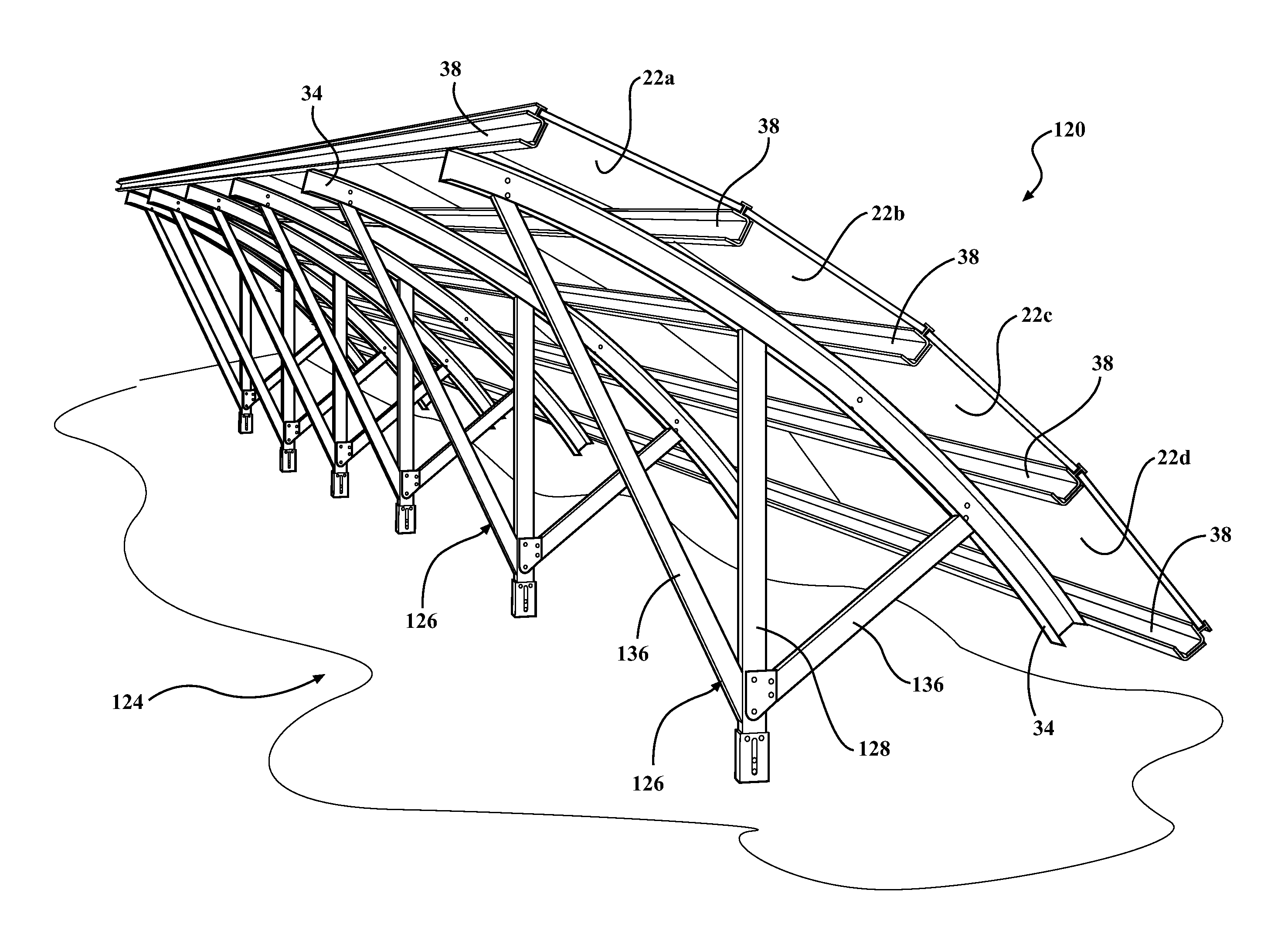
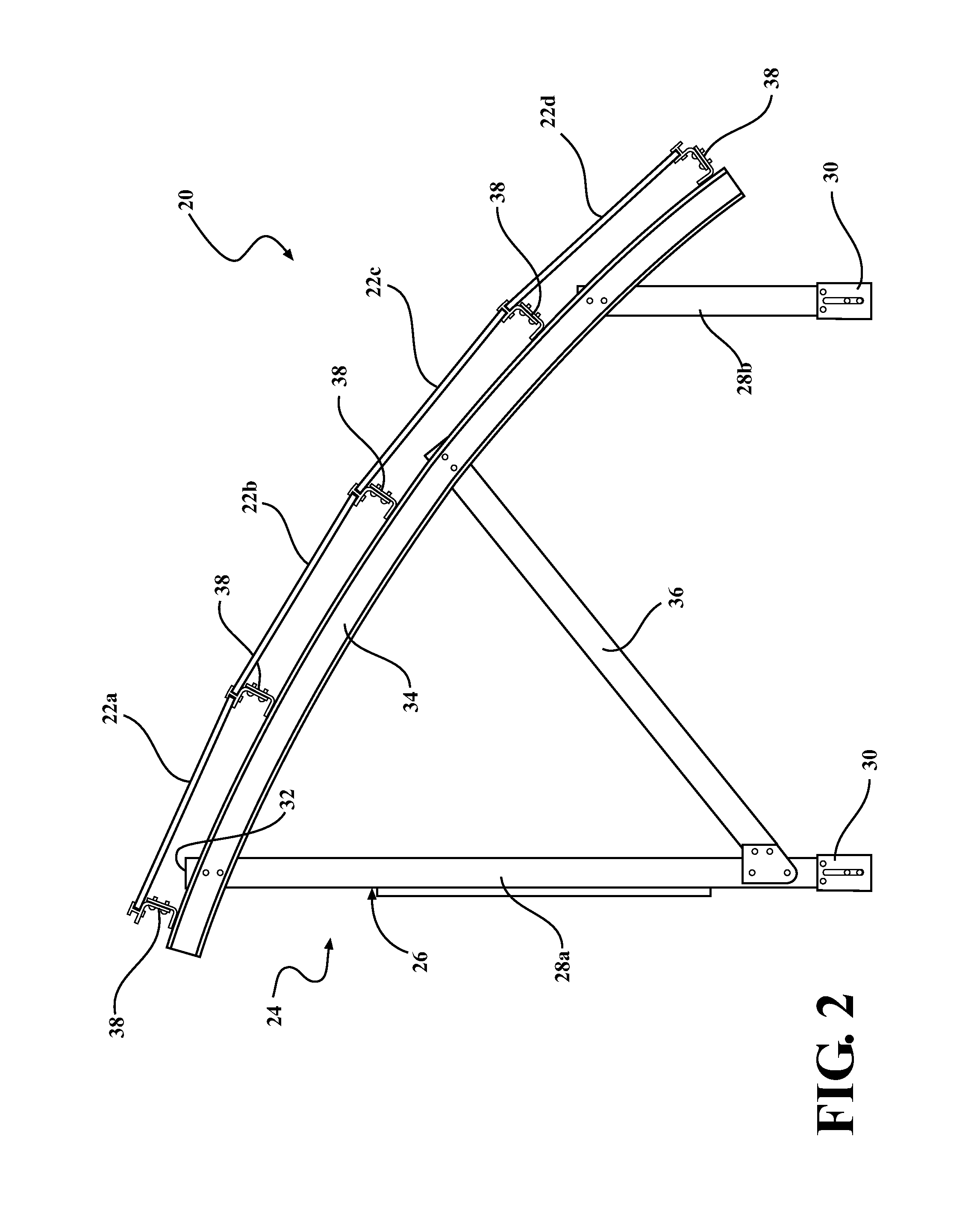
[0031]Referring to the Figures, wherein like numerals indicate corresponding parts throughout the several views, a first exemplary embodiment of a solar assembly 20 for harnessing potential energy from solar rays and generating electricity is generally shown in FIG. 2. The solar assembly 20 includes a plurality of solar panels arranged in a plurality of arrays 22a, 22b, 22c, 22d which are supported by a stationary mounting structure 24. In the exemplary embodiment, the solar panels are photovoltaic (PV) cells that are configured to receive solar radiation and convert it into electrical power. However, it should be appreciated that any other type of solar panel capable of converting potential energy from solar rays into electricity or any other form of useable energy could alternately be employed.

[0032]Referring now to FIG. 3, the mounting structure 24 of the first exemplary embodiment includes a plurality of sub-assemblies 26 spaced from one another in a lateral direction, which is ...


PUM


Abstract

A solar assembly for harnessing solar rays and generating electricity is provided. The solar assembly includes a mounting structure with a pair of sub-assemblies spaced from one another in an east-west direction and each having at least one post and a north-south rail. A plurality of east-west rails extend between the north-south rails of adjacent sub-assemblies. A plurality of photovoltaic (PV) arrays are attached to the east-west rails. The north-south rails of the sub-assemblies are curved concave downwardly towards the base such that the PV arrays are disposed at different angles from one another with the upper-most array being disposed at the shallowest angle relative to the base and the lower-most array being disposed at the steepest angle relative to the base.

Description

CROSS-REFERENCE TO PRIOR APPLICATION[0001]This U.S. National Stage Patent Application claims priority to International Application No. PCT / CA2012 / 000872 filed Sep. 20, 2012 which claims the benefit of U.S. Provisional Patent Application Ser. No. 61 / 537,610 filed Sep. 22, 2011, entitled “Solar Panel Assembly,” the entire disclosures of the applications being considered part of the disclosure of this application and hereby incorporated by reference.BACKGROUND OF THE INVENTION[0002]1. Field of the Invention[0003]The subject invention is related to a solar panel assembly, and more precisely to a solar panel assembly including a mounting structure for solar panels.[0004]2. Description of the Prior Art[0005]Solar power is becoming an increasingly popular alternative to fossil fuels for generating electricity. In general, solar power generators harness the potential energy of solar radiation and convert that potential energy into electricity. Some solar power generators utilize an array of...

Claims


Application Information

Patent Timeline
Patent Type & Authority Applications(United States)
IPC IPC(8): H01L31/042
CPCH01L31/0422F24S40/85F24S25/12F24S40/40F24S2020/16F24S2025/806H02S20/00H02S20/10Y02E10/47Y02E10/50
Inventor WERNER, MARK F.
Owner MAGNA INTERNATIONAL INC
Why Eureka
Try Eureka