Antenna structure for use with a horizontally polarized signal

a technology of antenna structure and horizontal polarization, applied in the field of antennas, can solve the problems of increasing aerodynamic drag, increasing the operating cost of the aircraft, and difficult to build, and achieve the effect of reducing the number of beam patterns that can be selected

Active Publication Date: 2020-01-14
FIRST RF CORP
View PDF3 Cites 3 Cited by
  • Summary
  • Abstract
  • Description
  • Claims
  • Application Information

AI Technical Summary

Benefits of technology

[0005]An antenna structure with back-to-back, quarter-wave patch antennas can be used to achieve a relatively thin antenna structure that, in particular applications, avoids the need for a T-shaped radome. To elaborate, the distance between the radiator patches of an antenna structure with back-to-back, quarter-wave patch antennas substantially defines the width of the antenna structure. While the width of the antenna structure can be as large as 3λL / 4 (where λL is the wavelength associated with the frequency that defines the low end of the bandwidth of the combined antennas), the width can preferably be less than λL / 2 and more preferably less than λL / 5. When the width of the antenna structure is relatively small and the antenna structure is used in an aircraft application or similar application, the need for a T-shaped radome to house the quarter-wave patch antennas is substantially eliminated and a blade-shaped radome with a more aerodynamic profile can be employed.
[0007]An additional embodiment of the antenna structure includes back-to-back, quarter-wave patch antennas and a combiner-divider network for: (a) when the antennas are being used to receive a signal, combining the signals from the two feed points associated with the antennas into a single signal that can be applied to a receiver or transceiver and (b) when the antennas are being used to transmit a signaling, dividing a signal from a transmitter or transceiver into two signals, one for each of the two feed points associated with the antennas. In a preferred embodiment that facilitates processing of an omnidirectional, horizontally polarized beam, the combiner-divider include a phase-shifter that, in operation, imparts a 180° phase shift to the signal associated with the feed point of one of the back-to-back, quarter-wave antennas.
[0009]What has previously been described as two, quarter-wave patch antennas or back-to-back, quarter-wave patch antennas will, for convenience, frequently be referred to hereinafter as an antenna pair or pair of antennas. It has been found that an antenna structure having two of these antenna pairs can be used to process horizontally polarized signal having a selected one of: (a) an omnidirectional, beam pattern, (b) forward end-fire beam pattern, (c) an aftward end-fire beam pattern, (d) a port side beam pattern, and (e) a starboard side beam pattern by appropriate control of each of the four feed points in such an antenna structure. As such, when the antenna structure is mounted to an aircraft and the axis of the antenna structure is substantially parallel to the roll axis of the aircraft, a forward beam extends from the antenna structure towards the nose of the aircraft; an aftward beam extends from the antenna structure towards the tail of the aircraft; a port side beam extends from the antenna structure towards the port side wing; and a starboard side beam extends from the antenna structure towards the starboard side wing. In many embodiments in which a monolithic structure supplies all of the grounds, the axis of the antenna is a line that is in the plane of the monolithic structure and intersects two lines, one line connecting the feed points associated with one back-to-back antenna pair and the other line connecting the feed points associated with the other back-to-back antenna pair. The control associated with each of the feed points involves being able to turn “on” (i.e., connect) or “off” (i.e., disconnect) the feed point and, with respect to a feed point that is turned “on,” apply one of two phase shifts to whatever signal the feed point is carrying. It should be appreciated that one of these two phase shifts could be a 0° phase shift. Further, by appropriately limiting the control (on / off and phase shift) that can be applied to the feed points, the number of beam patterns that can be selected can be reduced. For instance, by turning “on” each of the four feed points and applying a single, specific phase shift to the signals associated each of the four feed points, the antenna structure could be limited to processing, for example, only a forward end-fire beam pattern. The following describes three antennas structures that each include two pairs of antennas and can be used to generate any of the five above-noted beam patterns. Also described is an antenna structure that can be used to generate three of the five above-noted beam patterns and a composite forward-aftward beam pattern.
[0010]One embodiment of an antenna structure that includes two pairs of antennas has the shorting structures of one of the two pairs of antennas located between the radiator patches of the two pairs of antennas, the radiator patches of the other of the two pairs of antennas located between shorting structures of the first and second pairs of antennas, the ground planes of the two pairs of antennas substantially aligned, and the radiator patches of the two pairs of antennas substantially aligned with one another. It should be appreciated that various differences in the structures associated with each of the quarter-wave patch antennas in a pair of antennas, the orientation of the quarter-wave patch antennas forming a pair of antennas, and the orientation of the two pairs of antennas to one another can be tolerated and horizontally polarized signal operation with any one of the five possible patterns still achieved.
[0011]Another embodiment of an antenna structure that includes two pairs of antennas employs an isolator structure. In a particular embodiment, the isolator structure is positioned between the two pairs of antennas, the radiator patches of the two pairs of antennas are positioned between the shorting structures of the two pairs of antennas, the ground planes of the two pairs of antennas are substantially aligned, and the radiator patches of the first of the two pairs of antennas are substantially aligned with the radiator patches of the second of the two pairs of antennas. In this embodiment, the isolator structure has an “I” shape with each of the cross-bars at the top and bottom of “I” being substantially aligned with one of the radiator patches associated with each of the two pairs of antennas. It should be appreciated that various differences in the structures associated with each of the quarter-wave patch antennas in a pair of antennas, the orientation of the quarter-wave patch antennas forming a pair of antennas, and the orientation of the two pairs of antennas to one another can be tolerated and horizontally polarized signal operation with any one of the five possible beam patterns still achieved.
[0013]Yet another embodiment of an antenna structure that employs to two pairs of antennas is capable of processing an omnidirectional beam pattern, a port side beam pattern, a starboard side beam pattern, and a “combined” forward-aftward beam pattern by appropriate control of each of the four feed points associated with the antenna structure. In this embodiment, the antenna structure employs two pairs of antennas with the shorting structures of the two pairs of located between the radiator patches of the two pairs of antennas, the ground planes of the two pairs of antennas substantially aligned, and the radiators structures of the two pairs of antennas substantially aligned with one another. It should be appreciated that various differences in the structures associated with each of the quarter-wave antennas in a pair of antennas, the orientation of the quarter-wave antennas forming a pair of antennas, and the orientation of the two, pairs of antennas to one another can be tolerated and horizontally polarized signal operation with any one of the possible modes still achieved.

Problems solved by technology

Such radomes are costly to manufacture, difficult to build, and can increase aerodynamic drag (thereby increasing the operating expense of the aircraft).

Method used


Image

  • Antenna structure for use with a horizontally polarized signal
  • Antenna structure for use with a horizontally polarized signal
  • Antenna structure for use with a horizontally polarized signal

Examples


Embodiment Construction

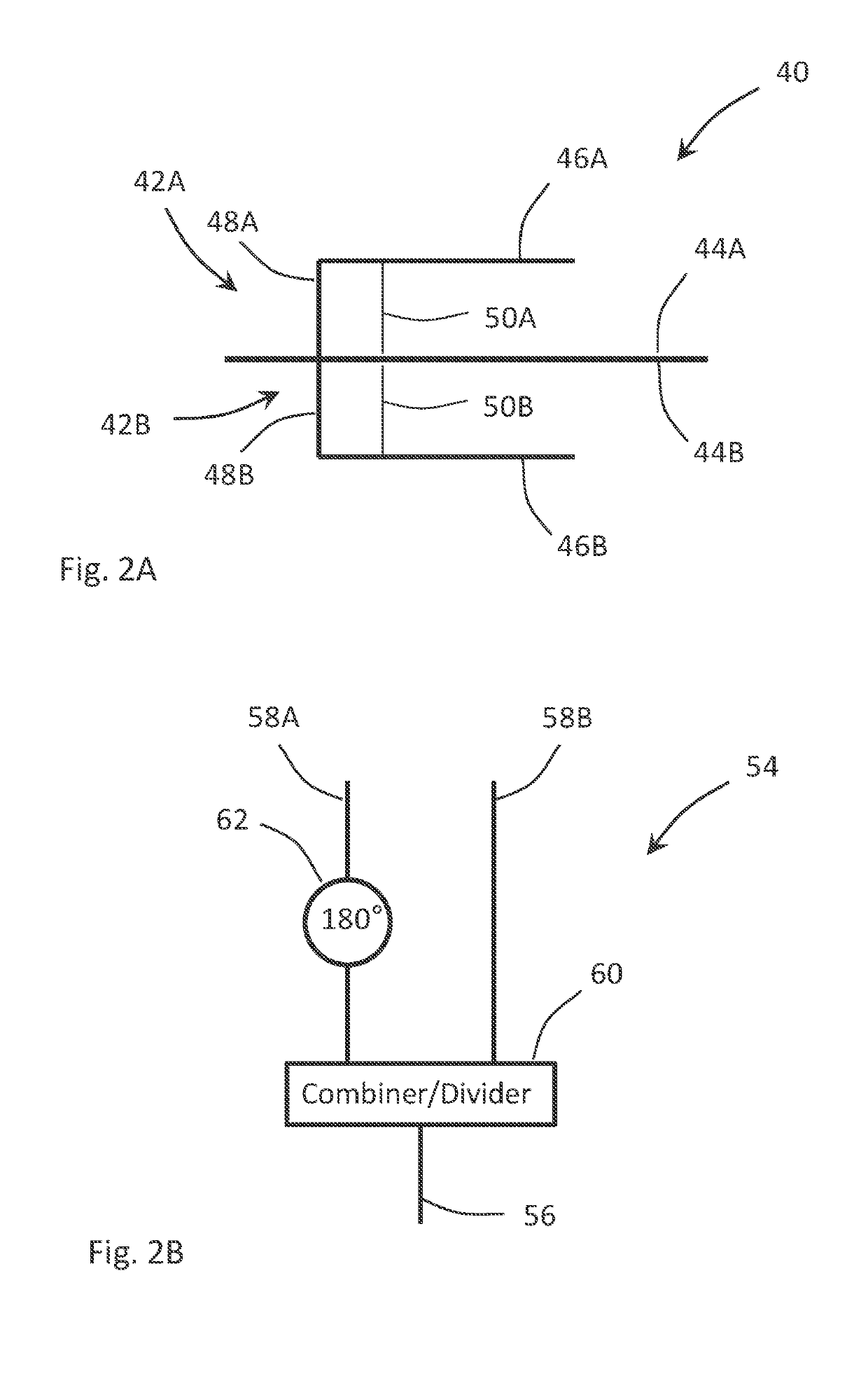
[0031]The invention is directed to an antenna structure capable of processing an omnidirectional, horizontally polarized signal. Common to each embodiment of the antenna structure is at least one pair of quarter-wave patch antennas. To facilitate the description of these antenna structures, a single quarter-wave patch antenna is initially described.

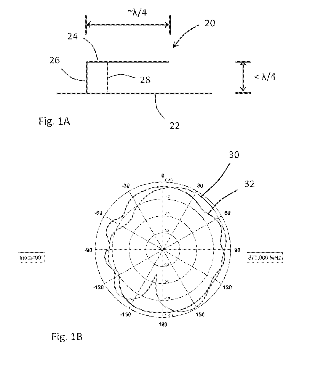
[0032]With reference to FIGS. 1A and 1B, a quarter-wave patch antenna 20 and the operation of such an antenna are described. The quarter-wave patch antenna 20 includes a ground plane 22, a radiator patch 24, a shorting structure 26 for electrically connecting the ground plane 22 and the radiator patch 24, and a feed point 28 that provides the electrical connection for conveying a signal to and / or from the radiator patch 24. Further, the greatest horizontal distance (as measured along the ground plane 22) from a point at which the shorting structure 26 establishes an electrical connection with the ground plane 22 to a point associated with...


PUM


Abstract

The invention is directed to an antenna structure for producing a horizontally polarized beam. In one embodiment, the antenna structure includes a first quarter-wave patch antenna and a second quarter-wave patch antenna that are positioned such that the ground planes of the patch antennas or a ground plane shared by the patch antennas is disposed between the patches of the two antennas and the shorting structures associated with the antennas are substantially aligned. In operation, the antenna structure is capable of processing an omni-directional, horizontally polarized beam.

Description

FIELD OF THE INVENTION[0001]The invention relates to antennas and, more specifically, to an antenna structure adapted to provide a horizontally polarized beam.BACKGROUND OF THE INVENTION[0002]Presently, antenna structures for generating an omnidirectional, horizontally polarized beam are used in a number of applications, including on aircraft where the antenna structures are mounted either on the top or bottom surfaces of the fuselage. In such applications, the antenna structure generally includes: (a) a planar radiator structure, (b) a feed structure for conveying a signal between the radiator structure and an interface associated with the aircraft, the feed structure having a length that allows the radiator structure to be positioned a desired distance away from the exterior surface of the aircraft, and (c) a support structure that serves to support the radiator structure at a desired distance away from the exterior of the aircraft. More specifically, when the aircraft is position...

Claims


Application Information

Patent Timeline
Patent Type & Authority Patents(United States)
IPC IPC(8): H01Q1/28H01Q1/42H01Q21/06H01Q3/34H01Q9/04H01Q1/48H01Q1/52H01Q9/06H01Q9/20H01Q1/30H01Q9/18H01Q9/16
CPCH01Q1/523H01Q1/42H01Q9/0421H01Q1/28H01Q1/48H01Q21/065H01Q21/067H01Q3/34H01Q1/30H01Q9/065H01Q9/20H01Q9/18H01Q1/285H01Q1/282H01Q1/286H01Q1/287H01Q1/281H01Q9/16H01Q3/06H01Q3/12H01Q9/40H01Q9/42H01Q21/28H01Q25/005
Inventor LALEZARI, FARZINGOULDER, MICHAEL R.
Owner FIRST RF CORP
Why Eureka
Try Eureka