Centrifugal compressor and turbocharger

a centrifugal compressor and turbocharger technology, which is applied in the direction of machines/engines, mechanical equipment, liquid fuel engines, etc., can solve the problems of limiting the diameter reduction of the boss portion, and achieve the effect of improving the surge margin and simple structur

Active Publication Date: 2020-02-27
MITSUBISHI HEAVY IND ENGINE & TURBOCHARGER LTD
View PDF0 Cites 2 Cited by
  • Summary
  • Abstract
  • Description
  • Claims
  • Application Information

AI Technical Summary

Benefits of technology

[0047]According to at least one embodiment of the present invention, there is provided a centrifugal compressor whereby it is possible to both improve the surge margin and ensure the choked flow rate with a simple structure.

Problems solved by technology

However, since the impeller is fastened to a rotational shaft by screwing the rotational shaft inserted in the boss portion with a nut, there is a limit to the reduction in diameter of the boss portion.

Method used


Image

  • Centrifugal compressor and turbocharger
  • Centrifugal compressor and turbocharger
  • Centrifugal compressor and turbocharger

Examples


Embodiment Construction

[0062]Embodiments of the present invention will now be described in detail with reference to the accompanying drawings. It is intended, however, that unless particularly identified, dimensions, materials, shapes, relative positions and the like of components described in the embodiments shall be interpreted as illustrative only and not intended to limit the scope of the present invention.

[0063]For instance, an expression of relative or absolute arrangement such as “in a direction”, “along a direction”, “parallel”, “orthogonal”, “centered”, “concentric” and “coaxial” shall not be construed as indicating only the arrangement in a strict literal sense, but also includes a state where the arrangement is relatively displaced by a tolerance, or by an angle or a distance whereby it is possible to achieve the same function.

[0064]For instance, an expression of an equal state such as “same”“equal” and “uniform” shall not be construed as indicating only the state in which the feature is strict...


PUM


Abstract

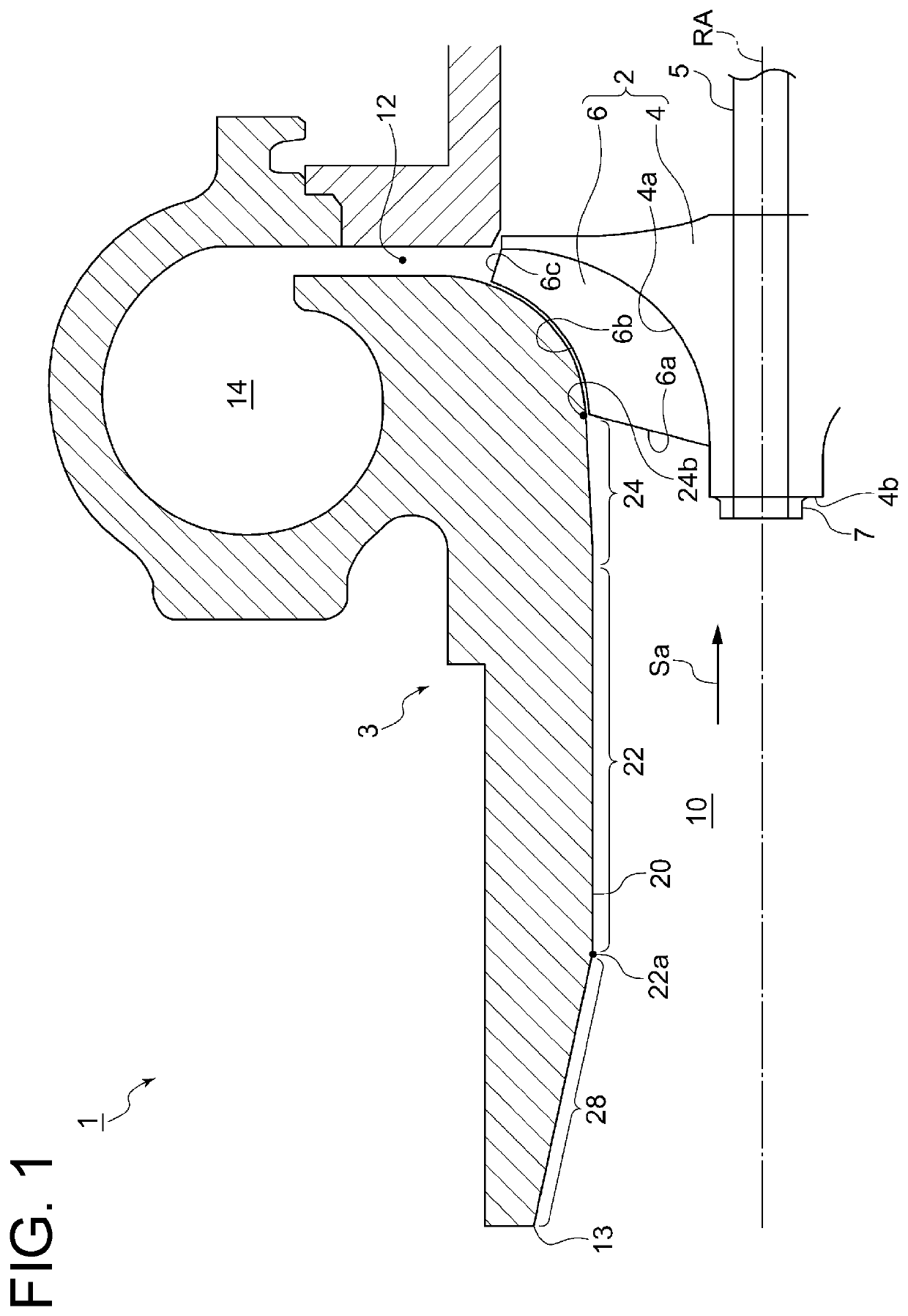
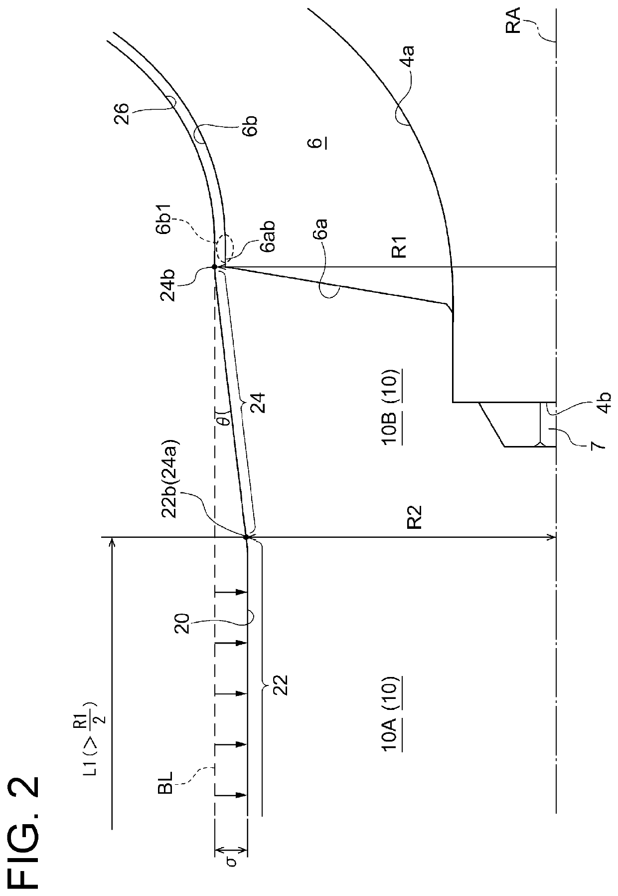
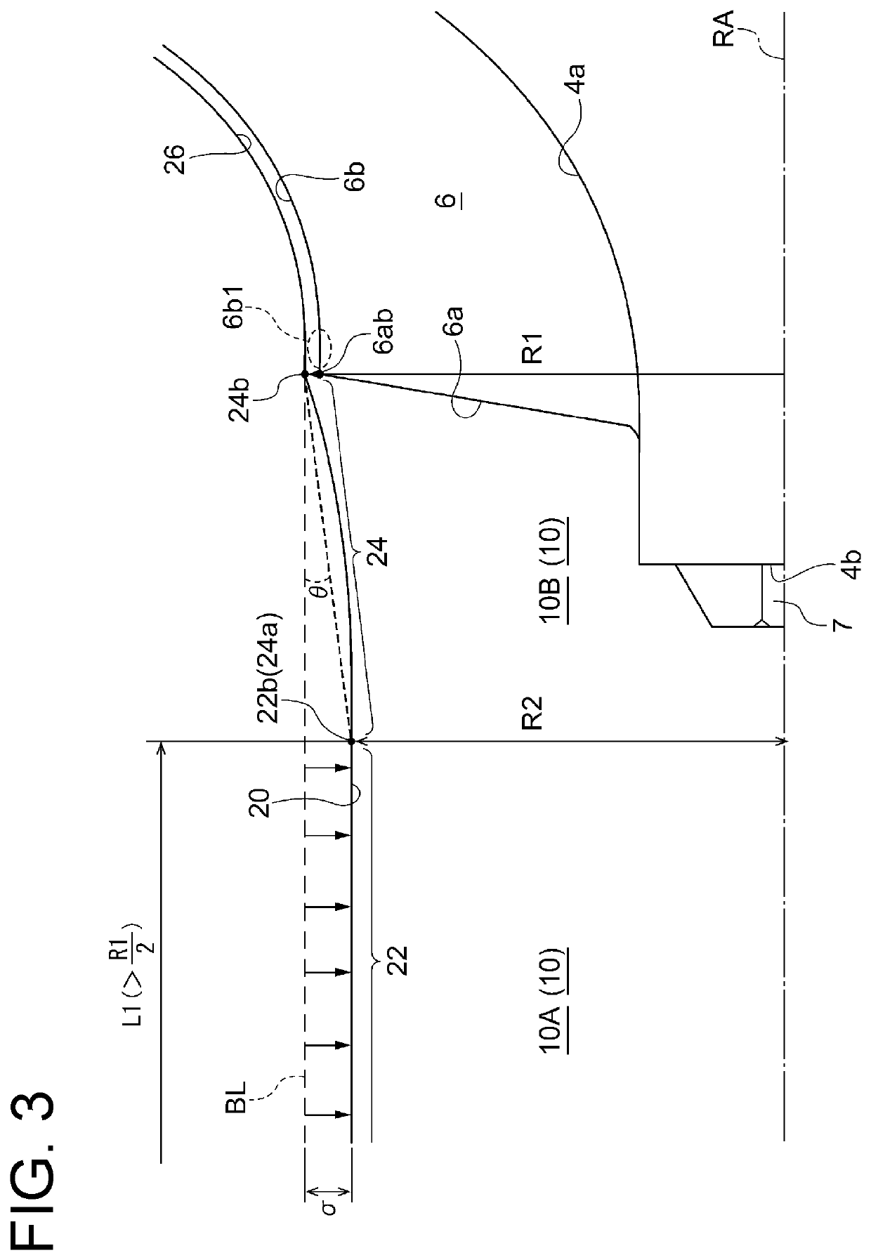
A centrifugal compressor includes an impeller including a hub and a plurality of blades disposed on an outer peripheral surface of the hub at intervals in a circumferential direction, and a casing accommodating the impeller and defining an inlet passage for introducing air along an axial direction of the impeller. An inner peripheral surface of the inlet passage includes a narrowed portion, and an inclined portion connected to a downstream side of the narrowed portion and having a radial distance from a rotational axis of the impeller gradually increasing toward the vicinity of tips of leading edges of the blades. Further, 0.01R1≤σ≤0.1R1 is satisfied, where R1 is radial distance between a downstream end of the inclined portion and the rotational axis, R2 is radial distance between a downstream end of the narrowed portion and the rotational axis, and σ is constriction amount which is a difference between R1 and R2.

Description

TECHNICAL FIELD[0001]The present disclosure relates to a centrifugal compressor and a turbocharger including the same.BACKGROUND ART[0002]In recent years, downsizing of engines equipped with a turbocharger has become common in the field of automobile engines, as a technique to reduce fuel consumption. Further, in recent years, a method for evaluating fuel consumption of automobile pays attention to extremely low speed or acceleration which is near to actual operating conditions of an engine. Accordingly, a wide-range and high-efficiency turbocharger enabling operation in a low-flow-rate operating region close to the surge line is desired.[0003]One solution to the wide range and high efficiency in a low-flow-rate operating region is to reduce the outer diameter of the impeller. In the low-flow-rate operating region, backflow (surging) occurs at the inlet of the impeller. The development of this backflow can be prevented by reducing the outer diameter of the impeller and the circumfer...

Claims


Application Information

Patent Timeline
Patent Type & Authority Applications(United States)
IPC IPC(8): F04D29/30F04D17/10
CPCF04D29/4206F04D29/444F04D17/10F05D2220/40F05D2250/51F04D29/30F04D29/284F04D29/4213F04D29/685F04D29/441Y02T10/12
Inventor IWAKIRI, KENICHIROHAYASHI, YOSHIHIRO
Owner MITSUBISHI HEAVY IND ENGINE & TURBOCHARGER LTD
Why Eureka
Try Eureka