Integrated Structure of Refluxer and Pressure Diffuser, and Centrifugal Compressor

a centrifugal compressor and refluxer technology, applied in the field of centrifugal compressors, can solve the problems of low assembly efficiency and large energy loss, and achieve the effects of improving compression efficiency, increasing gas pressure, and relatively high gas temperatur

Active Publication Date: 2020-02-27
GREE ELECTRIC APPLIANCES INC
View PDF0 Cites 0 Cited by
  • Summary
  • Abstract
  • Description
  • Claims
  • Application Information

AI Technical Summary

Benefits of technology

[0027]8. The centrifugal compressor of the present invention has at least two stages, and an accommodating space is disposed between the return device portion of the front stage and the second-stage impeller of the subsequent stage; the accommodating space is in communication with the gas supplying passage, and the gas supplying passage is configured to supply gas into the accommodating space, thereby improving the compression efficiency; when the centrifugal compressor is applied in a refrigerating apparatus, after the gas is compressed, the gas pressure is increased, and the gas temperature is relatively high; at this time, the gas supplying passage is in communication with an expansion valve, which enables a part of the refrigerant expanded by the expansion valve to flow into the accommodating space, thereby performing the functions of not only supplying gas, but also lowering the temperature.

Problems solved by technology

Therefore, the technical problem to be solved by the present invention is to overcome the technical defects that, the return device in the prior art, as a separate component, is connected with the pressure diffuser by screws, pins or welding, which will result in low assembly efficiency and a large energy loss.

Method used


Image

  • Integrated Structure of Refluxer and Pressure Diffuser, and Centrifugal Compressor
  • Integrated Structure of Refluxer and Pressure Diffuser, and Centrifugal Compressor
  • Integrated Structure of Refluxer and Pressure Diffuser, and Centrifugal Compressor

Examples


first embodiment

The First Embodiment

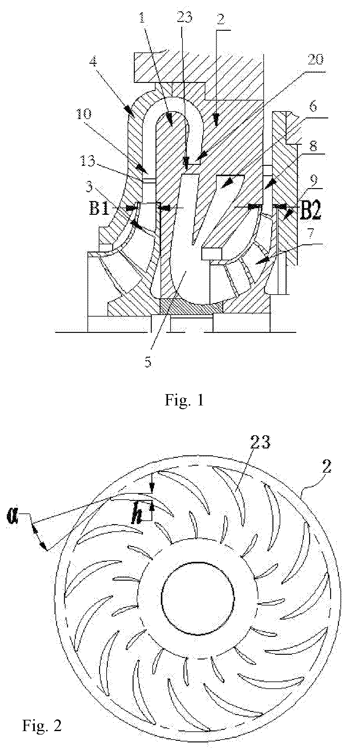
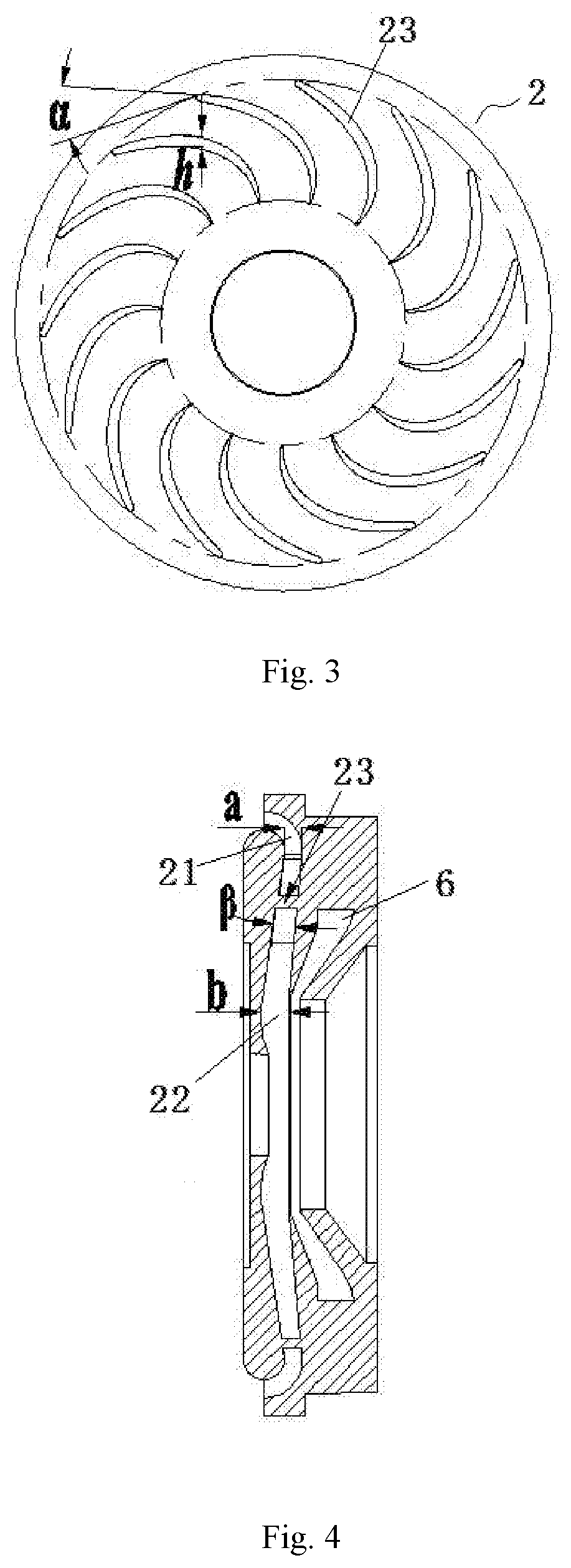
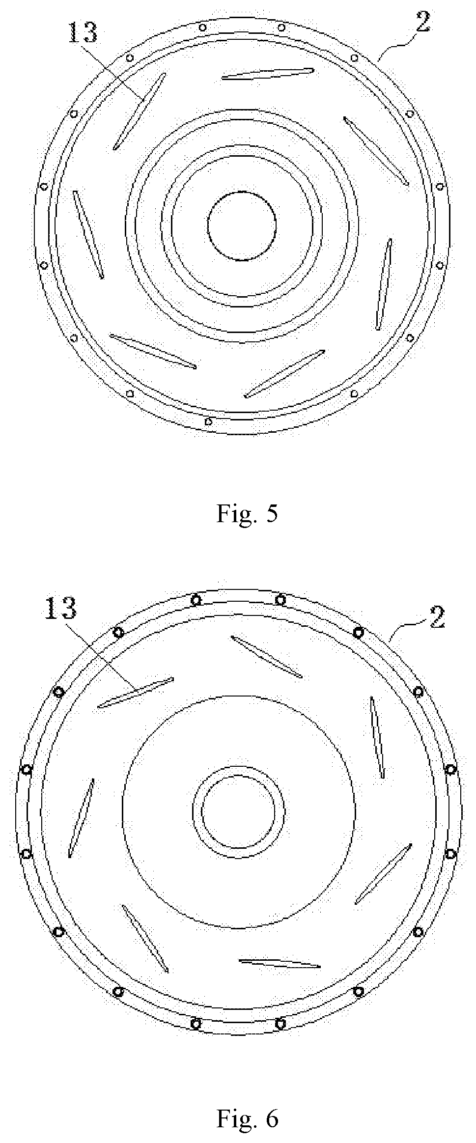
[0040]This embodiment provides an integrated structure of a return device and a pressure diffuser. As shown in FIG. 1, the integrated structure includes a pressure diffuser portion 1 and a return device portion 2 integrally molded with the pressure diffuser portion 1. The pressure diffuser portion 1 is configured to form a pressure diffusion flow channel 10. The return device portion 2 has a return channel 20. The return channel 20 is in communication with the pressure diffusion flow channel 10, and is configured to guide the gas from the pressure diffusion flow channel 10.

[0041]In the integrated structure of the return device and the pressure diffuser of the embodiment, the pressure diffuser portion 1 and the return device portion 2 are integrated to be one component, which is no longer a prior art structure formed by secondarily connecting and integrating a separate pressure diffuser and a separate return device with screws, pins or welding. With such a configu...

second embodiment

The Second Embodiment

[0049]This embodiment provides a centrifugal compressor, including a main shaft, an impeller 3 installed on the main shaft, and a pressure diffuser cover plate 4, and further including the integrated structure described in the first embodiment; the pressure diffuser cover plate 4 is opposite to the pressure diffuser portion 1 to form the pressure diffusion flow channel 10.

[0050]The centrifugal compressor of this embodiment employs the integrated structure above, therefore it has all of the advantages brought by the integrated structure above.

[0051]The centrifugal compressor has two stages, and an accommodating space 5 is disposed between the return device portion 2 of the front stage and the second-stage impeller 7 of the subsequent stage. The accommodating space 5 is in communication with the gas supplying passage 6, and the gas supplying passage 6 is configured to supply gas into the accommodating space 5, thereby improving the compression efficiency.

[0052]The...


PUM


Abstract

An integrated structure of a return device and a pressure diffuser, and a centrifugal compressor are provided. The structure includes a pressure diffuser portion and a return device portion integrally molded with the pressure diffuser portion. The pressure diffuser portion is configured to form a pressure diffusion flow channel. The return device portion has a return channel. The return channel is in communication with the pressure diffusion flow channel, and is configured to guide gas from the pressure diffusion flow channel. The structure of the present invention eliminates a need of independently installing a return device and a pressure diffuser, and eliminates connection seams caused by assembly and misalignment caused by accumulated errors. Therefore, gas can smoothly flow through the pressure diffusion flow channel into the return channel, such that a gas flow is well guided, and the gas flow uniformity is better.

Description

CROSS-REFERENCE TO RELATED APPLICATIONS[0001]This application is a US 371 Application from PCT / CN2017 / 103127 filed Sep. 25, 2017, which claims priority to Chinese Application No. 201611102983.5 filed Dec. 5, 2016, the technical disclosures of which are hereby incorporated herein by reference.TECHNICAL FIELD[0002]The invention relates to the technical field of a centrifugal compressor, and particularly, to an integrated structure of a return device and a pressure diffuser, and a centrifugal compressor.BACKGROUND[0003]A centrifugal compressor, also known as a radial flow compressor, is widely used in various processes, mainly for conveying air, various process gases or mixed gases, and increasing their pressure. The multi-stage centrifugal compressor generally includes a main shaft, a first-stage impeller, a first-stage pressure diffuser cover plate, a first-stage pressure diffuser, a return device, a second-stage impeller, a second-stage pressure diffuser cover plate, and a second-st...

Claims


Application Information

Patent Timeline
Patent Type & Authority Applications(United States)
IPC IPC(8): F04D29/44F04D17/12
CPCF04D29/444F04D17/122F04D29/441F04D29/5846F05D2230/21F04D29/023F04D29/684
Inventor ZHANG, ZHIPINGZHONG, RUIXINGJIANG, NANJIANG, CAIYUNCHEN, YUHUILIU, ZENGYUELEI, LIANDONGZHOU, YILIU, JIANFEI
Owner GREE ELECTRIC APPLIANCES INC
Why Eureka
Try Eureka