Camera module with thermal deformable material

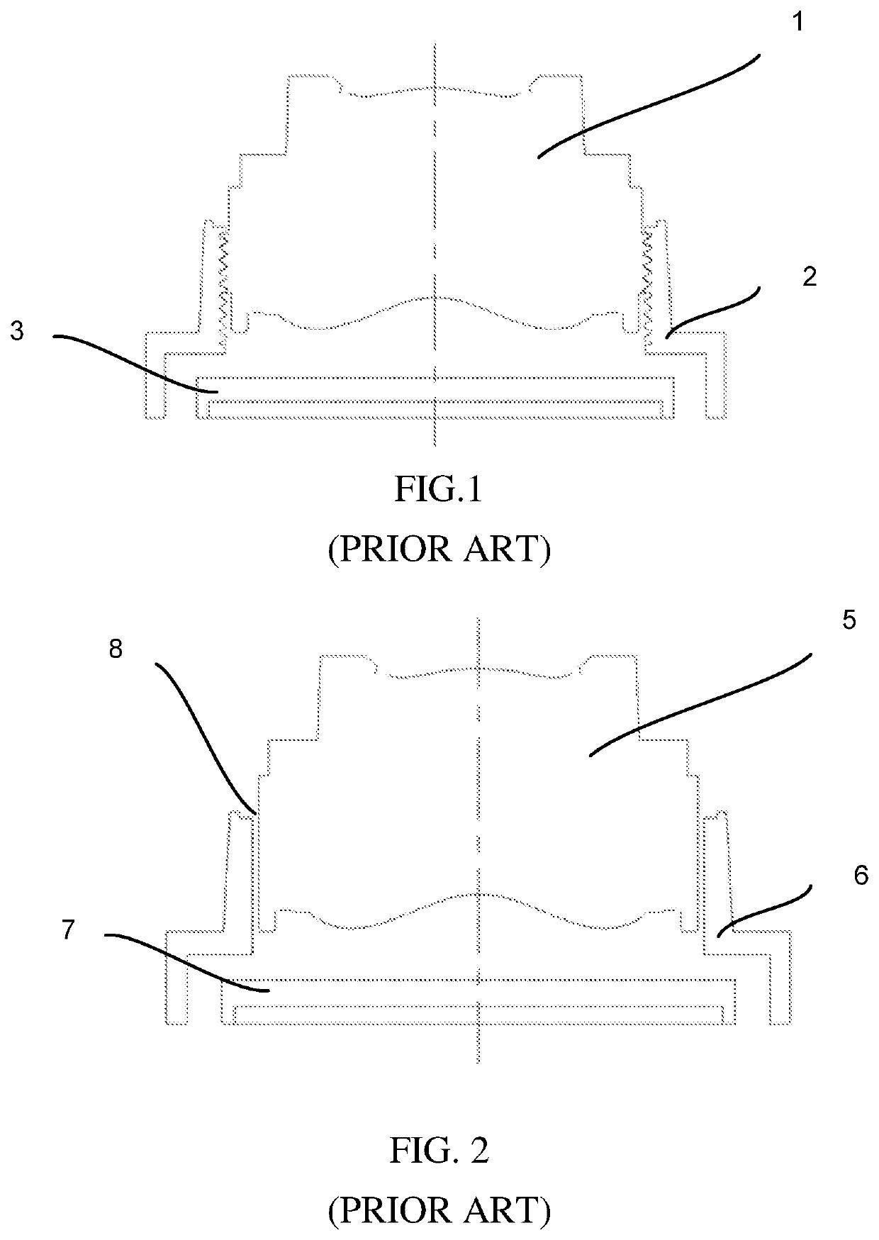
a technology of thermal deformation and camera module, which is applied in the field of camera modules, can solve the problems of difficult combination of lens barrel b>5/b> and holder b>6, labor consumption in the back-end process, and the difficulty of threadless combination transport, so as to achieve the effect of saving costs and being disassembled

Active Publication Date: 2020-02-27
SPRING RAINBOW OPTICS CO LTD
View PDF0 Cites 0 Cited by
  • Summary
  • Abstract
  • Description
  • Claims
  • Application Information

AI Technical Summary

Benefits of technology

[0039]In summary, in accordance with an embodiment of the present disclosure, the camera module includes the thermal deformable material filled in a gap between the lens barrel and the holder, (1) preventing the lens barrel and the holder from trembling during the transportation process, (2) blocking dust from entering the gap between the lens barrel and the holder, and (3) allowing the adjustment of the lens barrel with respect to the holder during the focus adjusting process, due to the flexibility of the thermal deformable material. Moreover, (4) the layer of the thermal deformable material separates the lens barrel from the dispensed glue. Therefore, after the lens barrel and the holder are fixed by the glue, if the re-adjustment between the lens barrel and the holder is desired due to the unsatisfied focus adjustment result, the lens barrel can still be disassembled from the holder by simply removing the layer of the thermal deformable material from the lens barrel without damaging the lens barrel, and then rewrapping the thermal deformable material around the lens barrel for the next round of assembling steps. Therefore, rework and saving costs are both achieved.

Problems solved by technology
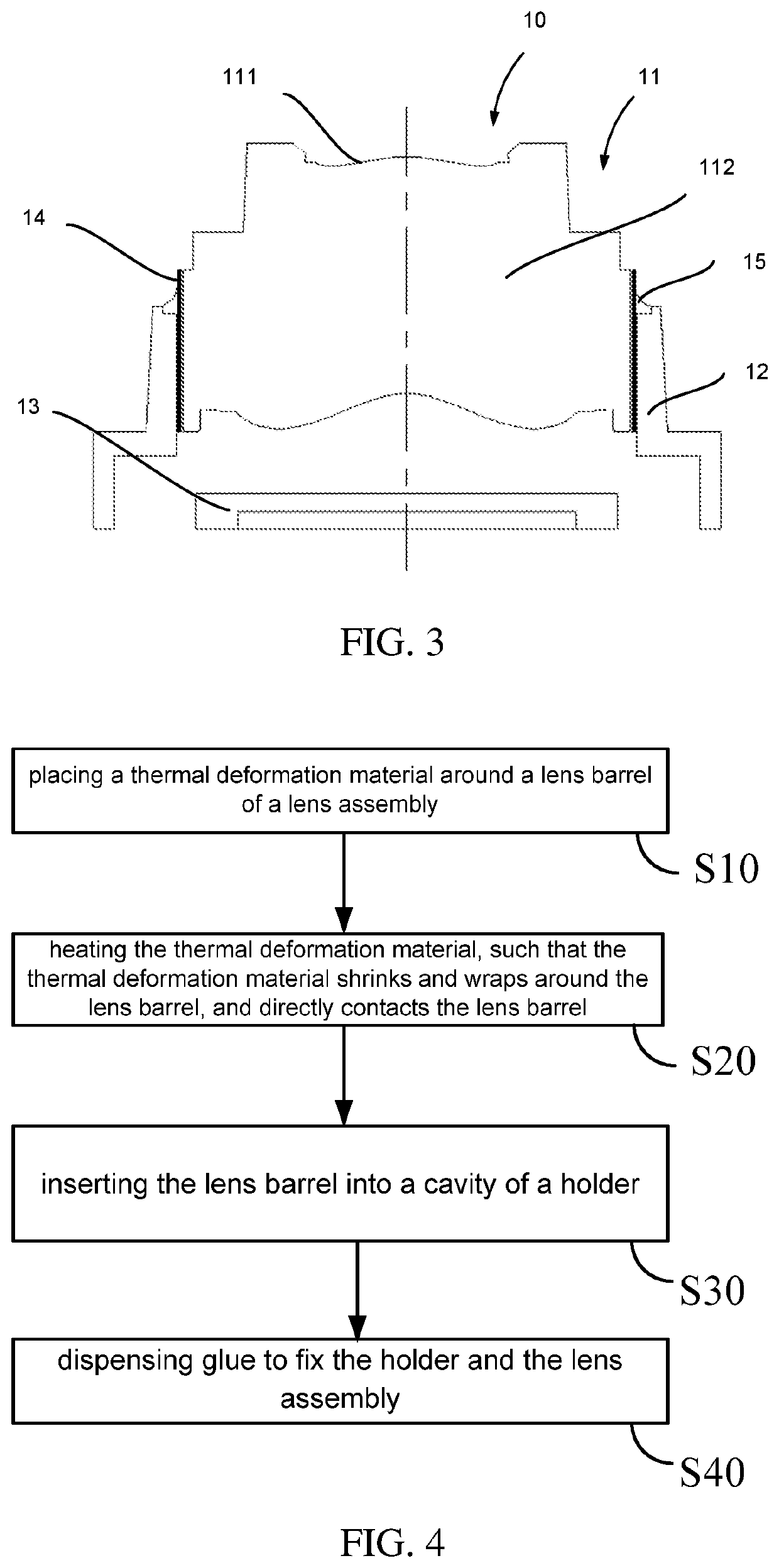
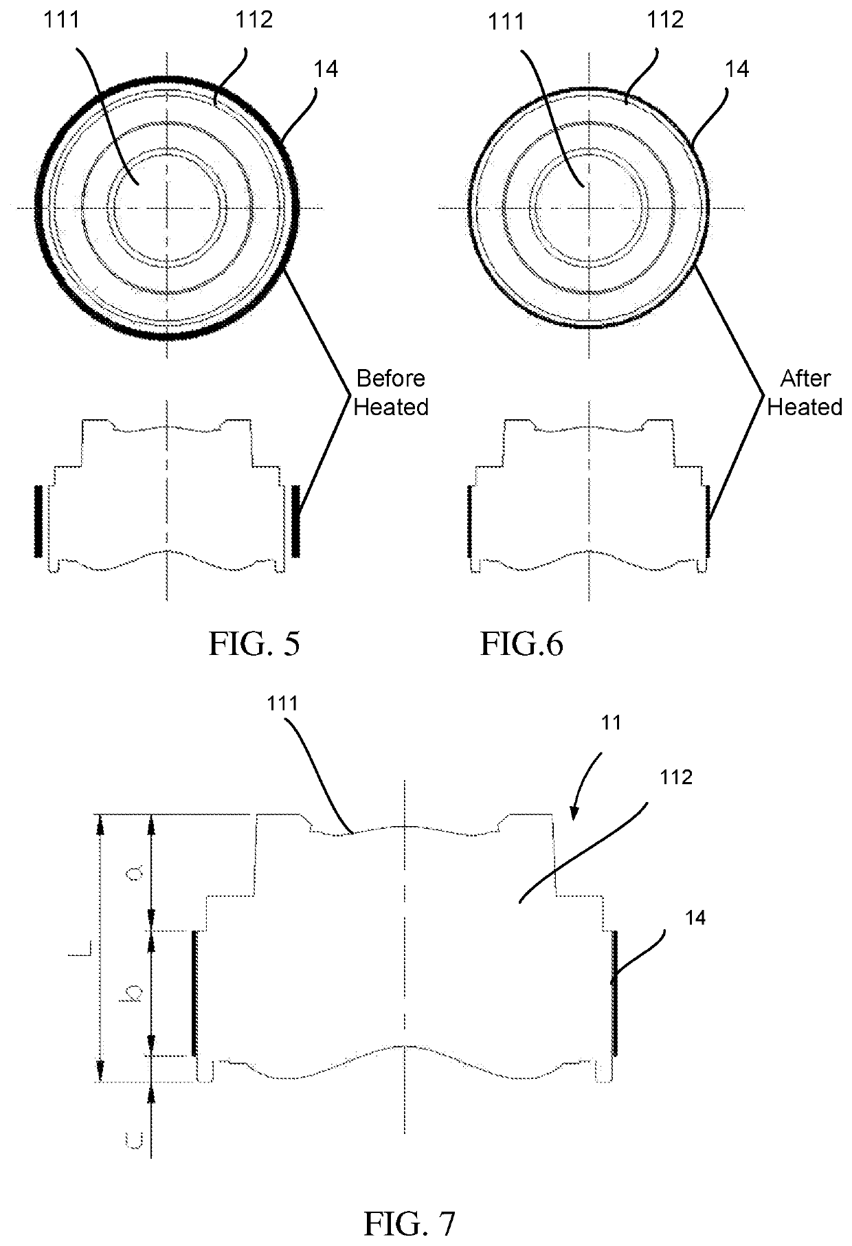
This threadless combination has two problems.
Firstly, the lens barrel 5 and the holder 6 are difficult to transport in combination.
Due to the gap, the lens barrel 5 and the holder 6 tend to tremble during the transportation process, unlike the thread type combination, in which the lens barrel 1 and the holder 2 are pre-locked in advance, resulting in labor consumption in the back-end process.
Moreover, dust and the like may easily enter the gap 8 between the lens barrel 5 and the holder 6 during the transportation process, resulting in defects in the resultant image.
Secondly, after the focus is adjusted, the combination is fixed by glue.
However, if the focus adjustment result is not accurate enough, there is no chance of rework, because strong binding of the glue makes the lens barrel 5 and the holder 6 difficult to separate.

Method used


Image

  • Camera module with thermal deformable material
  • Camera module with thermal deformable material
  • Camera module with thermal deformable material

Examples


Embodiment Construction

[0049]The following description of the embodiments with reference to the accompanying drawings is used to illustrate particular embodiments of the present disclosure. The directional terms used in the present disclosure, such as “upper”, “lower”, “front”, “back”, “left”, “right”, “inner”, “outer”, “side surface”, etc., are only directions with regard to the accompanying drawings. Therefore, the directional terms used for describing and illustrating the present disclosure are not intended to limit the present disclosure.

[0050]In the drawings, units with similar structures are indicated by the same reference number.

[0051]As to an “embodiment” mentioned herein, the particular features, structures, or characteristics described in this embodiment, which may be described in combination with the embodiment, may be included in at least one embodiment of the present disclosure. The phrases appearing at various locations in the specification do not necessarily refer to the same embodiments, n...


PUM


Abstract

A camera module includes a lens assembly, a holder, and a thermal deformable material. The lens assembly includes at least one lens and a lens barrel, wherein the lens barrel includes a wall surrounding a central axis of the lens assembly to define a receiving chamber, and the lens is disposed in the receiving chamber. The holder surrounds the lens barrel and supports the lens assembly. The thermal deformable material is disposed between an outer wall of the lens barrel and an inner wall of the holder.

Description

CROSS REFERENCE TO RELATED APPLICATIONS[0001]The present application claims the benefit of priority under 35 USC 119(e) of U.S. Provisional Patent Application No. 62 / 720,608 entitled “IMAGING MODULE WITH HEAT SHRINKABLE MATERIAL” and filed on Aug. 21, 2018, the contents of which are incorporated herein by reference in their entirety.FIELD OF INVENTION[0002]The present disclosure relates to the technical field of cameras, and particularly to a camera module including a thermal deformable material.BACKGROUND OF DISCLOSURE[0003]The lens barrel 1 and the holder 2 in a conventional camera module are often combined in a thread engagement manner 4 as a screw and a nut, as shown in FIG. 1. However, recently, due to need of a focus adjusting process, a lens barrel 5 and a holder 6 are often combined in a threadless manner, as shown in FIG. 2. A small gap 8 is reserved between the lens barrel 5 and the holder 6 for filling glue in order to fixing the combination in the back end of the focus a...

Claims


Application Information

Patent Timeline
Patent Type & Authority Applications(United States)
IPC IPC(8): G02B7/02
CPCG02B7/025G02B7/021G02B7/023
Inventor CHIANG, PO-LIANGJHENG, YU-TENG
Owner SPRING RAINBOW OPTICS CO LTD
Why Eureka
Try Eureka