Electrode pad removal device and hammer

A technology for dismantling devices and electrode pads, which is applied in the direction of hand hammers, resistance welding equipment, multi-purpose hand tools, etc., can solve the problems of shortened overall length and inability to use, etc., to reduce workload, increase operation options, and achieve good efficiency Effect

Active Publication Date: 2018-07-06
KYOKUTOH
View PDF6 Cites 0 Cited by
  • Summary
  • Abstract
  • Description
  • Claims
  • Application Information

AI Technical Summary

Problems solved by technology

In addition, since the electrode pad that has been periodically cut will gradually become shorter in its overall length, it will eventually become unusable. Therefore, it is necessary to remove the electrode pad from the small diameter part of the welding torch within a specified time, and install a new electrode pad on the welding torch. On the small diameter part of the welding torch

Method used


Image

  • Electrode pad removal device and hammer
  • Electrode pad removal device and hammer
  • Electrode pad removal device and hammer

Examples


no. 1 approach

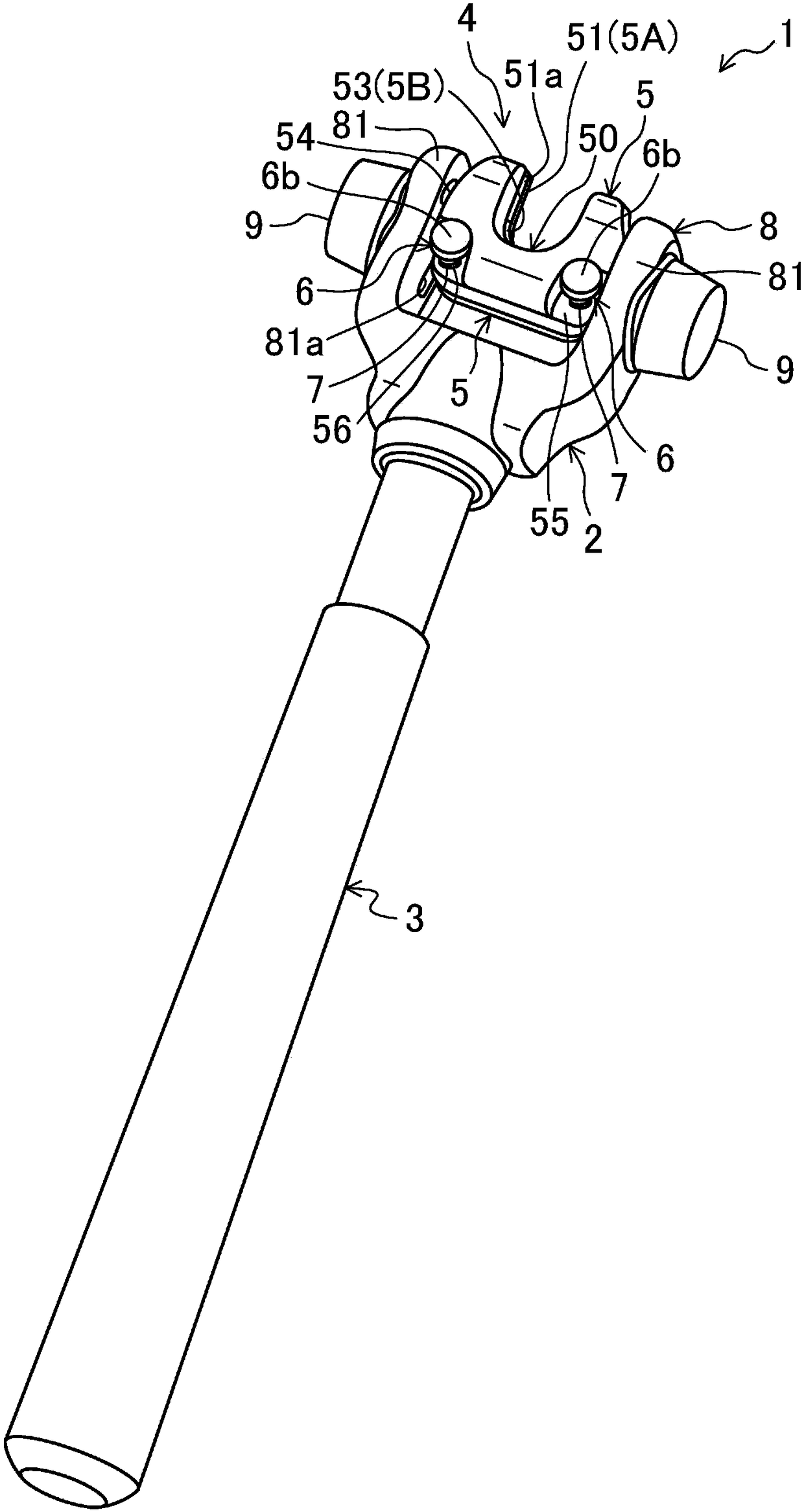
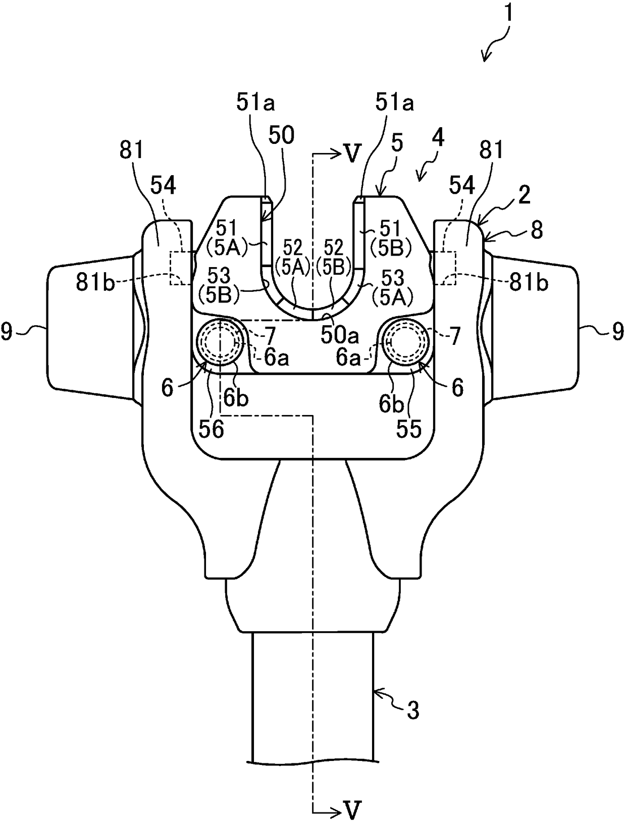
[0045] figure 1 and figure 2 The hammer 1 according to the first embodiment of the present invention is shown. like Figure 5 to Figure 7 As shown, the hammer 1 is used when detaching the electrode pad 12 from the tip of the welding gun 11 for spot welding, or when installing the electrode pad 12 on the tip of the welding gun 11 . The hammer 1 includes a hammer body 2 that is substantially in the shape of a "T" when viewed from above, and an operating rod 3 held by an operator during operation.

[0046] The welding torch 11 is a general welding torch that is held and used by an industrial robot (not shown). A cylindrical large-diameter portion 11 a and a cylindrical small-diameter portion 11 b are formed integrally at the tip of the welding torch 11 so that the central axis 11 c is the same.

[0047] The electrode pad 12 is installed on the small-diameter portion 11b by fitting, so that the central axis 12a of the electrode pad 12 is consistent with the central axis 11c o...

no. 2 approach

[0104] Figure 8 and Figure 9 A hammer 1 according to a second embodiment of the present invention is shown. The second embodiment differs from the first embodiment only in the following two points, and is the same as the first embodiment in other respects. That is, the structure of the second support portion 81b of the arm member 8 is different from the first embodiment, and the point that the hammer 1 is used with the electrode pad 12 of the welding torch 11 facing upward is different from the first embodiment. Therefore, only the differences from the first embodiment will be described in detail below.

[0105] In the second embodiment, the second support portion 81b of each protruding support portion 81 is in the shape of a groove that gradually approaches the side of the one detachable member 5 as it approaches the other end side of the arm member 8, and the second support portion 81b of each protruding support portion 81 The first support portion 81 a and the second s...


PUM


Abstract

A pair of detachment members (5) capable of approaching and separating from each other are provided, and the pair of detachment members (5) have respective claw portions (5A, 5B) and protrusions (54). Each claw (5A, 5B) can be inserted into the gap (S1) between the large-diameter portion (11a) and the electrode pad (12), and the protrusion (54) faces the insertion direction of each claw (5A, 5B) direction is highlighted. On one end side of the arm member (8), there are formed a first support portion (81a) for supporting the rotation of a protrusion (54) on a detachment member (5) and a rotation support portion (81a) for supporting the rotation of a protrusion (54) on another detachment member (5). The second support portion (81b). The first support portion (81a) has a groove shape that gradually approaches the other detachable member (5) side as it approaches the other end side of the arm member (8).

Description

technical field [0001] The invention relates to an electrode pad removal device and a hammer comprising the electrode pad removal device. Among them, the electrode pad detaching device detaches the electrode pad mounted on the tip of the welding torch for spot welding from the tip of the welding torch. Background technique [0002] Generally, a cylindrical large-diameter portion and a cylindrical small-diameter portion are formed on the top end of a welding torch for spot welding, the central axis of the small-diameter portion and the central axis of the large-diameter portion are the same central axis, and the small-diameter portion and the large-diameter portion are the same. The large diameter parts are connected together. An electrode pad is attached to the small-diameter portion by fitting so that a gap is formed between the electrode pad and the large-diameter portion. [0003] By the way, after welding for a predetermined number of times, the tip part of the electro...

Claims


Application Information

Patent Timeline
Patent Type & Authority Patents(China)
IPC IPC(8): B25B27/00B25D1/00
CPCB25B27/00B25D1/00B23K11/36B23K11/3072B23K31/02B25D1/02B25F1/006
Inventor 中嶋弘太郎
Owner KYOKUTOH
Why Eureka
Try Eureka