Torque Generating Device
a technology of torque generation and torque, which is applied in the direction of shock absorbers, couplings, mechanical devices, etc., can solve the problems of small number of elements that can be reused after a specification change, difficult to reliably collect the entire magnetorheological fluid filled between the elements, and disadvantageous in terms of manufacturing cost and design cost, so as to achieve cost reduction
- Summary
- Abstract
- Description
- Claims
- Application Information
AI Technical Summary
Benefits of technology
Problems solved by technology
Method used
Image
Examples
first embodiment
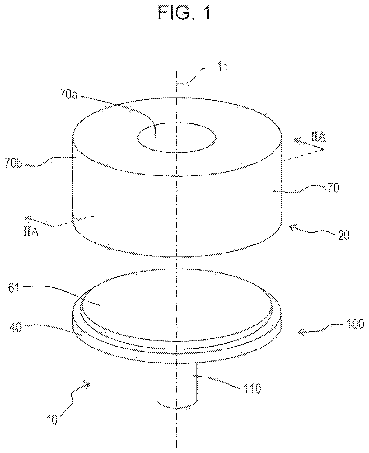
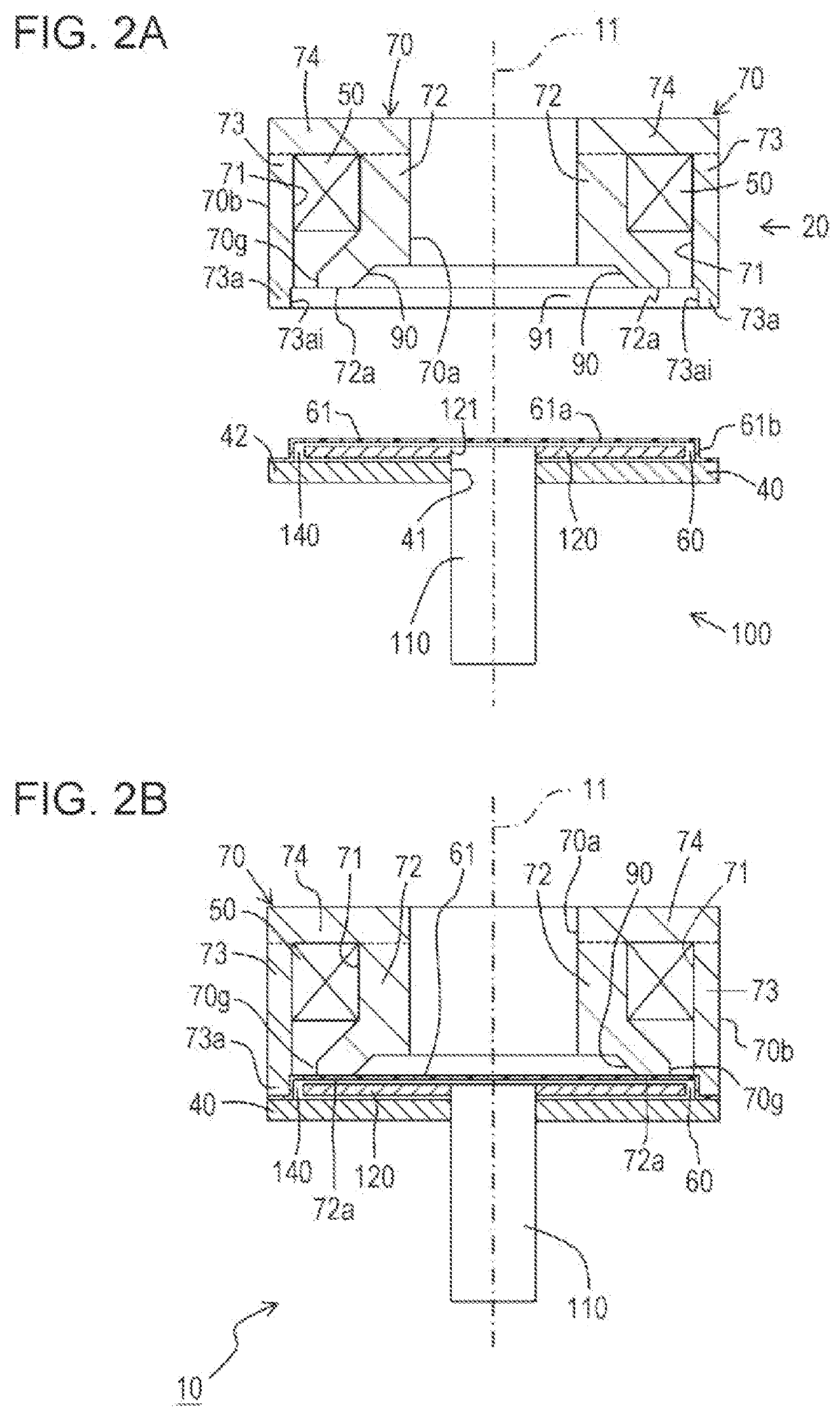
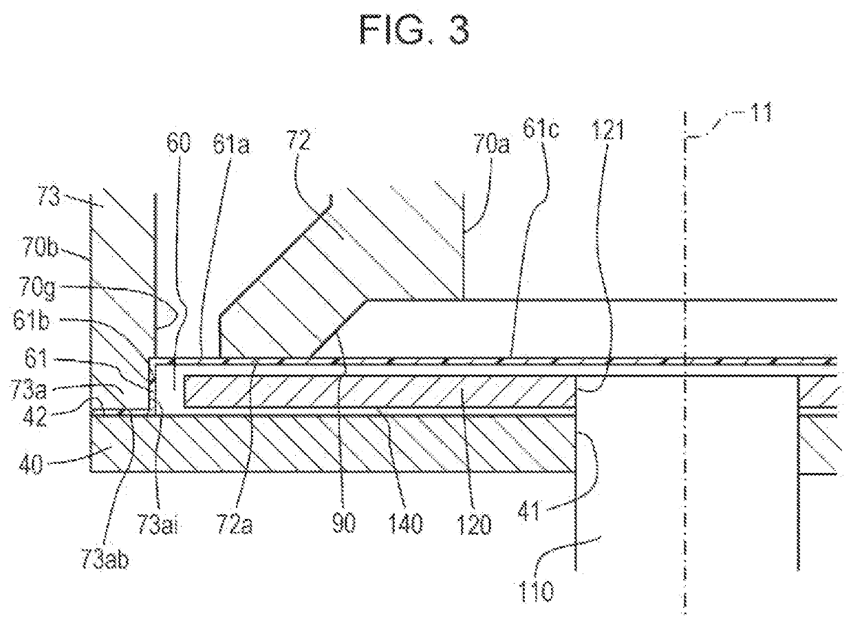
[0034]FIG. 1 is an exploded perspective view illustrating the configuration of a torque generating device 10 according to a first embodiment. FIG. 2A is a sectional view taken along line IIA-IIA illustrated in FIG. 1. FIG. 2B is a sectional view illustrating an assembled state of the torque generating device 10 illustrated in FIG. 2A. FIG. 3 is an enlarged sectional view of part illustrated in FIG. 2B. FIG. 4 is a sectional view corresponding to FIG. 2A, serving as an explanatory view conceptually illustrating a magnetic path based on a magnetic field generated by an excitation coil 50. FIG. 5 is a functional block diagram of the torque generating device 10.
[0035]In each of the drawings, for convenience of description, the up-down direction is defined along a central axis 11 of a shaft portion 110 (rotation shaft). However, this does not limit directions in actual use. A direction perpendicular to the central axis 11 from the central axis 11 is referred to as a radial direction. In ...
second embodiment
[0074]FIG. 6A is a sectional view illustrating the configuration of the torque generating device according to a second embodiment. FIG. 6B is a perspective view illustrating the configuration of a cover member 261 according to the second embodiment. FIG. 6A is a sectional view at a position corresponding to FIG. 2A. FIG. 6B is a perspective view when the cover member 261 is seen from above.
[0075]Preferably, according to the second embodiment, instead of the cover member 61 serving as the second sealing member and the adjuster according to the first embodiment, the cover member 261 (the second sealing member and the adjuster) having a bellows portion 262 (bellows structure) is provided. Other configurations are similar to those of the first embodiment, and the same members are denoted by the same reference signs.
[0076]As illustrated in FIG. 6B, the cover member 261 has a circular shape in plan view and is disposed between the excitation coil 50 (magnetic field generator) and the magn...
third embodiment
[0080]FIG. 7A is a sectional view illustrating the configuration of the torque generating device according to a third embodiment. FIG. 7B is an exploded perspective view illustrating the configuration of the torque generating device according to the third embodiment. FIG. 7A is a sectional view at a position corresponding to FIG. 2A. FIG. 7B is a perspective view when a cover member 361 serving as the second sealing member is seen from above.
[0081]Preferably, according to the third embodiment, instead of the cover member 61 serving as the second sealing member and the adjuster according to the first embodiment, the cover member 361 (the second sealing member and the adjuster) having a flexible deformation plate portion 362 is provided. Other configurations are similar to those of the first embodiment, and the same members are denoted by the same reference signs.
[0082]As illustrated in FIG. 7B, the cover member 361 has a circular shape in plan view and is disposed between the excitat...
PUM
 Abstract
Description
Claims
Application Information
 - R&D
- Intellectual Property
- Life Sciences
- Materials
- Tech Scout
- Unparalleled Data Quality
- Higher Quality Content
- 60% Fewer Hallucinations
Browse by: Latest US Patents, China's latest patents, Technical Efficacy Thesaurus, Application Domain, Technology Topic, Popular Technical Reports.
© 2025 PatSnap. All rights reserved.Legal|Privacy policy|Modern Slavery Act Transparency Statement|Sitemap|About US| Contact US: help@patsnap.com


