
Sensor array, apparatus for dispensing a vapor phase reactant to a reaction chamber and related methods

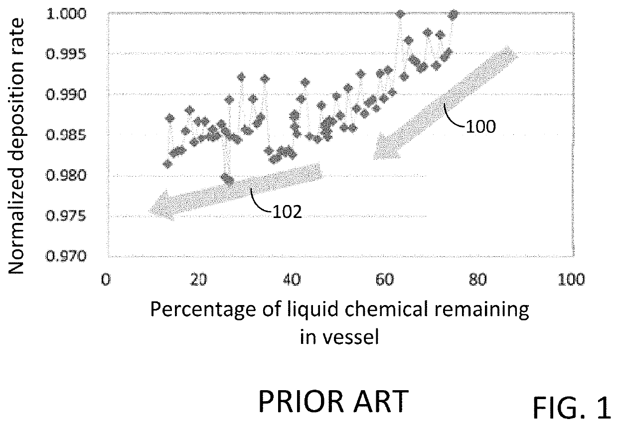
a technology of vapor phase reactant and sensor array, which is applied in the direction of coating, chemical vapor deposition coating, metallic material coating process, etc., can solve the problems of undesirable downtime, unfavorable re-charge of liquid chemical precursors, and undesirable variation

Active Publication Date: 2020-02-27
ASM IP HLDG BV
View PDF0 Cites 205 Cited by
  • Summary
  • Abstract
  • Description
  • Claims
  • Application Information

AI Technical Summary

Benefits of technology

The patent describes an apparatus and method for dispensing a vapor phase reactant to a reaction chamber. The apparatus includes a vessel for holding a liquid chemical, an array of sensors for measuring the level of the chemical, and an inlet for introducing a carrier gas and an outlet for dispensing the reactant. The sensor array is distributed within the vessel with an irregular vertical interval between adjacent sensors. This design allows for precise detection and control of the chemical level during use, resulting in more efficient and accurate reactions.

Problems solved by technology

However, there are some forms of liquid chemical precursor which are not readily adaptable for re-charge of the vessel.
In addition, the exchange of the discharged vessel for a full vessel may incur undesirable down time for the semiconductor processing apparatus and may also necessitate the need for safe storage of a large number of chemical vessels.
The increase in distance between the carrier gas inlet and the exposed surface of the liquid chemical can result in an unwanted variation in the vapor phase reactant flow out from the chemical vessel to the reaction chamber.
For example, as the liquid chemical within the vessel is consumed and the distance between the carrier gas inlet and the exposed surface of the liquid chemical increases, the flow of vapor phase reactant from the chemical vessel to the reaction chamber may decrease, resulting in an undesirable variation in semiconductor processing conditions.

Method used


Image

  • Sensor array, apparatus for dispensing a vapor phase reactant to a reaction chamber and related methods
  • Sensor array, apparatus for dispensing a vapor phase reactant to a reaction chamber and related methods
  • Sensor array, apparatus for dispensing a vapor phase reactant to a reaction chamber and related methods

Examples


Embodiment Construction

[0020]Although certain embodiments and examples are disclosed below, it will be understood by those in the art that the invention extends beyond the specifically disclosed embodiments and / or uses of the invention and obvious modifications and equivalents thereof Thus, it is intended that the scope of the invention disclosed should not be limited by the particular disclosed embodiments described below.

[0021]The illustrations presented herein are not meant to be actual views of any particular material, structure, or device, but are merely idealized representations that are used to describe embodiments of the disclosure.

[0022]As used herein the term “fill level” may refer to the vertical location of the upper exposed surface of a liquid chemical disposed within a vessel.

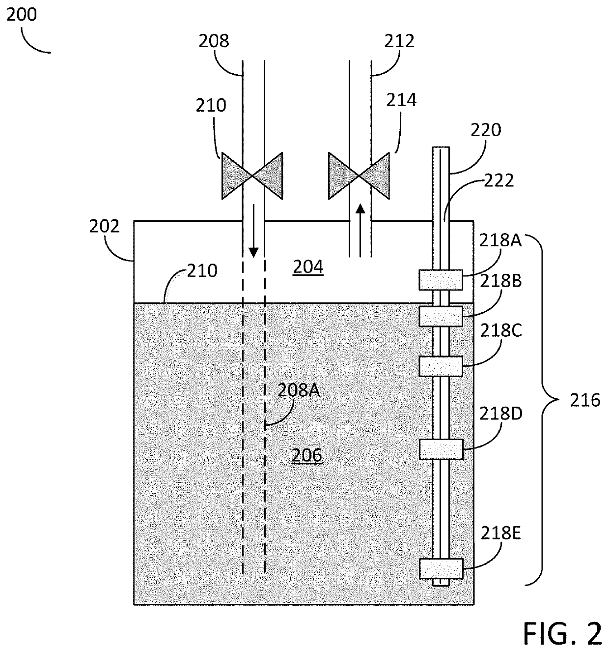
[0023]The embodiments of the disclosure may include apparatus and methods for dispensing a vapor phase reactant to a reaction chamber. In particular, the embodiments of the disclosure may include a vessel configured for...


PUM

PropertyMeasurementUnit
Temperatureaaaaaaaaaa
Concentrationaaaaaaaaaa
Volumeaaaaaaaaaa

Abstract

An apparatus for dispensing a vapor phase reactant to a reaction chamber is disclosed. The apparatus may include: a vessel having an inner volume configured to contain a liquid chemical; an array of sensors configured for detecting a fill level of the liquid chemical disposed within the inner volume, wherein the array of sensors are vertically distributed within the inner volume with an irregular vertical interval between adjacent sensors. The apparatus may also include: an inlet disposed in the vessel and configured for providing a carrier gas into the inner volume; and an outlet disposed in the vessel and configured for dispensing the vapor phase reactant from the inner volume to the reaction chamber. A sensor array for detecting the fill level of a liquid chemical is also disclosed, as well as methods for dispensing a vapor phase reactant to a reaction chamber.

Description

FIELD OF INVENTION[0001]The present disclosure relates generally to sensor arrays and an apparatus for dispensing a vapor phase reactant to a reaction chamber and in particular to an apparatus including a vessel for containing a liquid chemical, which includes an array of sensors configured for detecting the fill level of the liquid chemical. The disclosure also includes methods for dispensing a vapor phase reactant to a reaction chamber.BACKGROUND OF THE DISCLOSURE[0002]Semiconductor processing apparatus commonly use one or more vapor phase reactants, i.e., precursors, as source chemicals for performing semiconductor substrate processes, such as, for example, deposition, cleaning, and etching processes. The vapor phase reactants may be contained in a source vessel in a liquid state and are subsequently converted to a vapor state for transport to a reaction chamber associated with a semiconductor processing apparatus.[0003]High volume semiconductor fabrication facilities may utilize...

Claims


Application Information

Patent Timeline
IPC IPC(8): H01L21/67C23C16/448C23C16/52
CPCH01L21/67069C23C16/52C23C16/4481H01L21/67028H01L21/67017H01L21/67253C23C16/4482
Inventor SUSA, YOSHIO
Owner ASM IP HLDG BV
Features
  • Generate Ideas
  • Intellectual Property
  • Life Sciences
  • Materials
  • Tech Scout
  • Unparalleled Data Quality
  • Higher Quality Content
  • 60% Fewer Hallucinations
Learn More