Antenna device

Active Publication Date: 2020-02-27
YOKOWO CO LTD
View PDF0 Cites 3 Cited by
  • Summary
  • Abstract
  • Description
  • Claims
  • Application Information

AI Technical Summary

Benefits of technology

[0016]In the antenna device according to the invention, the linear element is provided on the first surface of the dielectric substrate, the slit antenna is provided on the second surface opposite to the first surface of the dielectric substrate, and the linear element and the slit antenna coupled to each other such that the linear element and a slit or

Problems solved by technology

In particular, a dipole antenna that is installed vertically has a problem that its radiation pattern is prone to be distorted due to the presence of the transmission line to deteriorate its performance because an antenna element and the t

Method used


Image

  • Antenna device
  • Antenna device
  • Antenna device

Examples


Example

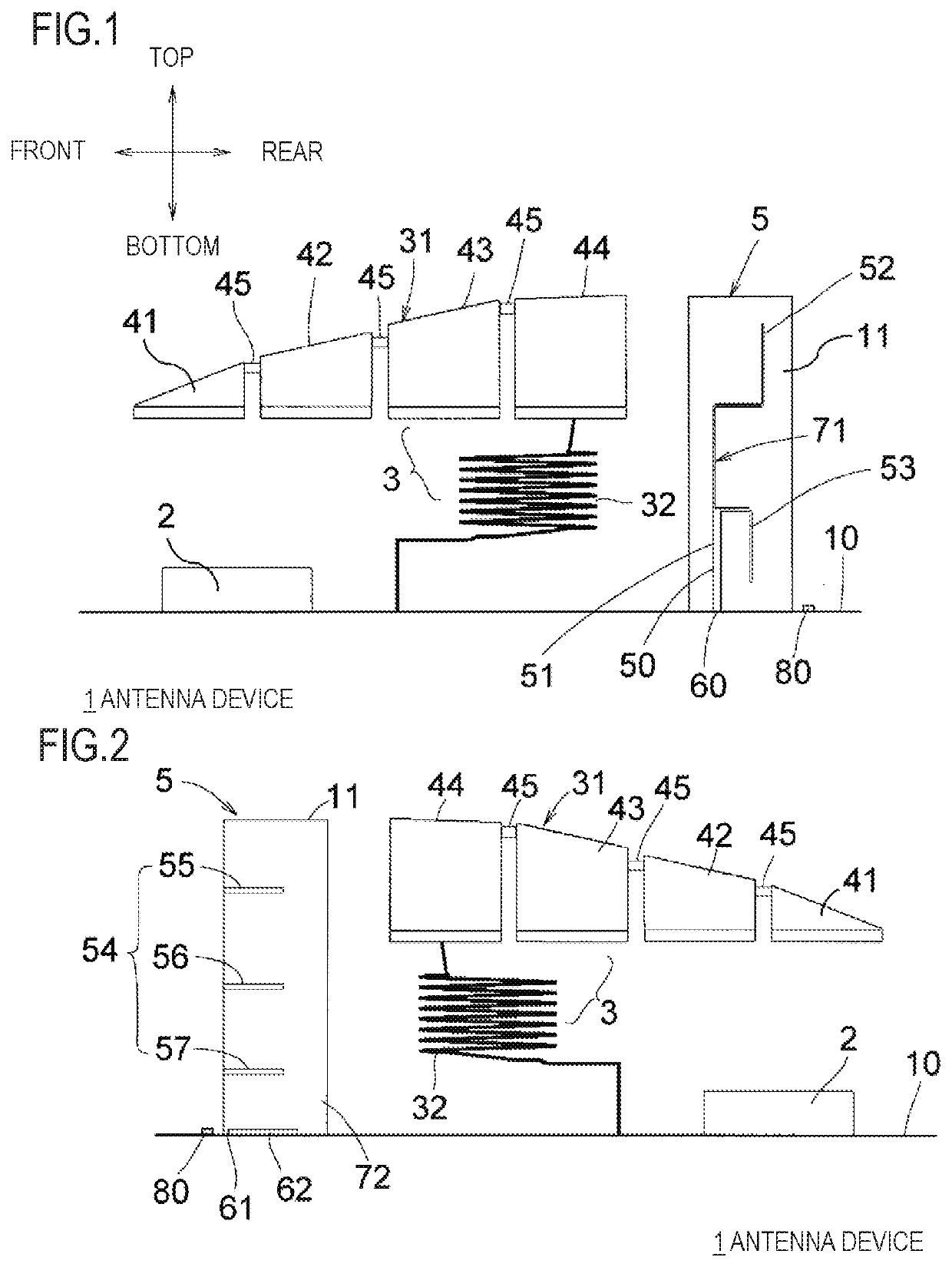
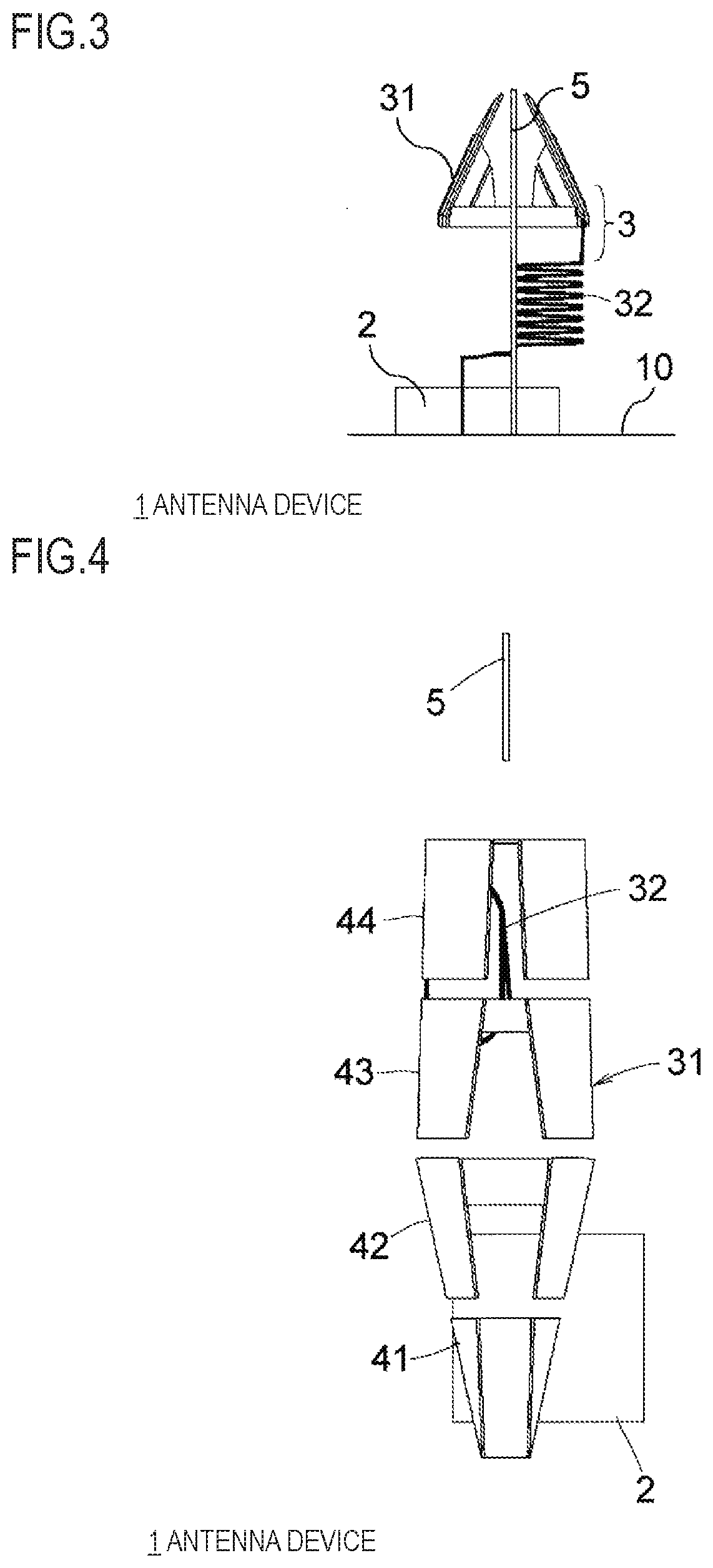
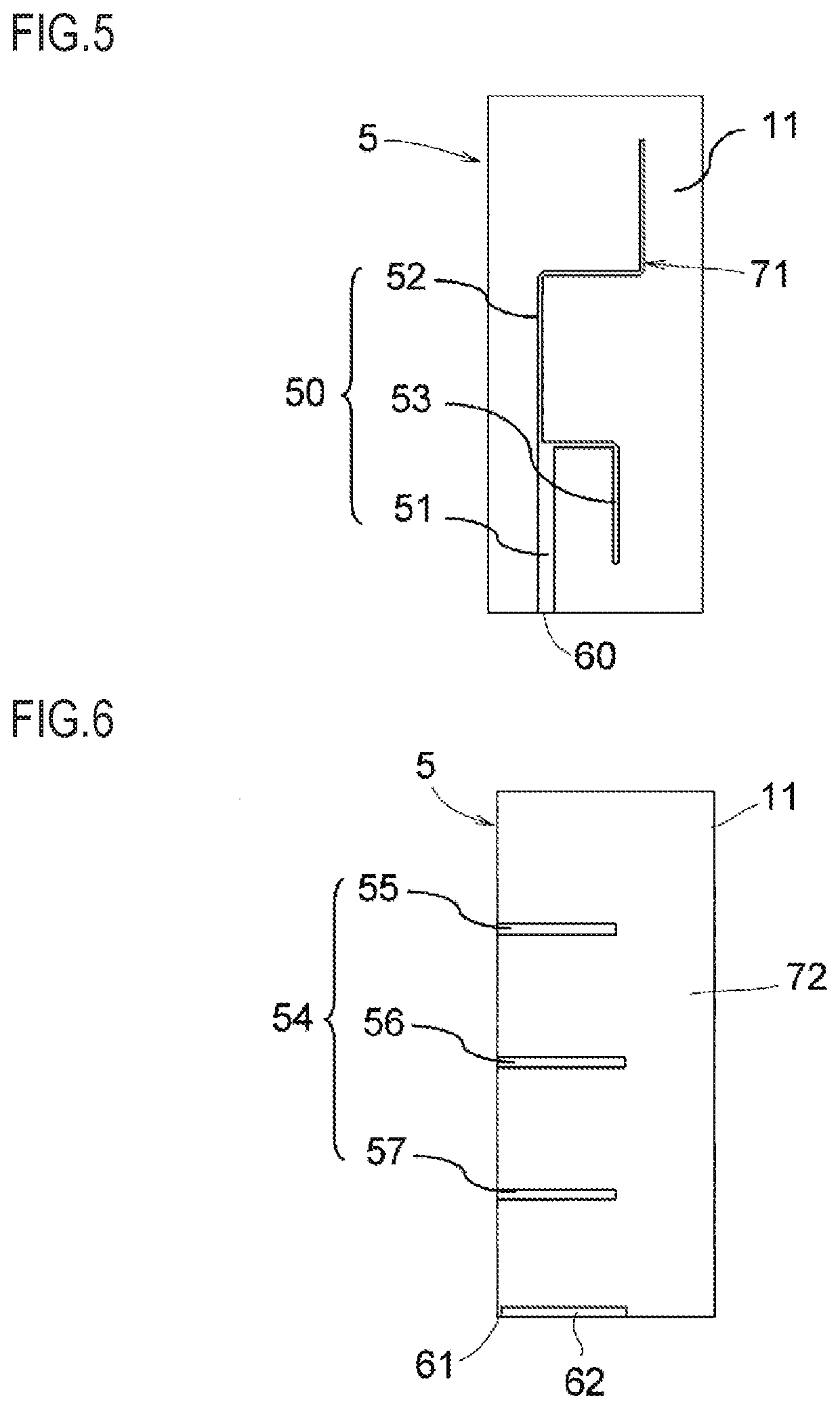
[0038]An antenna device according to a first embodiment of the invention will be described with reference to FIGS. 1-7. As shown in these drawings, in the antenna device 1, a GNSS antenna (a patch antenna) 2, an AM / FM broadcast reception antenna 3, and an antenna board 5 in which a V2X communication slit antenna is provided are installed on a circuit board 10 which is fixed to an antenna base (not shown), so as to be arranged in this order from the front side. The circuit board 10 has attachment members for fixing the GNSS antenna 2, the AM / FM broadcast reception antenna 3, and the antenna board 5. These constituent elements are housed in an internal space that is surrounded by the antenna base and a radio wave transmissive case (a radome) which covers the antenna base from above. The GNSS antenna 2, which is equipped with a radiation electrode provided on a top surface and has upward directivity, is fixed to the circuit board 10 via an attachment member. The GNSS antenna 2 may be f...

Example

Embodiment 2

[0060]FIG. 12 is an explanatory diagram showing an antenna board 5A employed in the second embodiment and is a superimposition of a left side view and a right side view of the antenna board 5A. Whereas the same slit antenna 54 as employed in the first embodiment is employed in the second embodiment, the second embodiment is different from the first embodiment in that the first branch linear element portion 52 and the second branch linear element portion 53 cross (overlap with) the firsts slit 55 and the second slit 57, respectively, from above to below. To make the first slit 55 and the second slit 57 in phase, it is necessary to set the first crossing portion 58 and the second crossing portion 59 in phase. To this end, the length of the first branch linear element portion 52 from the point where it branches off the common linear element portion 51 to the first crossing portion 58 is set equal to the length of the second branch linear element portion 53 from the point wh...

Example

[0063]FIGS. 14-16 show an antenna board 5B employed in a third embodiment of the present invention. The antenna board 5B is different from the antenna board 5 employed in the first embodiment in the shapes of the lower slit and the parasitic slit that constitute the slit antenna and the shape of the linear element is different than in the antenna board 5 accordingly. That is, a slit antenna 54A has a first slit 55, and parasitic slit 56A, and a second slit 57A, a front end portion of the parasitic slit 56A is bent upward and downward so that the parasitic slit 56A assumes a T-shape, and the second slit 57A is bent downward so as to assume an L shape. The sum of the length of the parasitic slit 56A in the front-rear direction and its length in the top-bottom direction is λ / 4. The length of the second slit 57A including the length of the bent portion is λ / 4. The second branch linear element portion 53 is also bent once additionally so as to be suitable for the shape of the second slit...


PUM


Abstract

An antenna device includes an antenna board in which a conductor pattern is provided on each of both surfaces of a dielectric substrate. A linear element is provided on a first surface of the dielectric substrate. A slit antenna is provided on a second surface of the dielectric substrate opposite to the first surface. When the first surface and the second surface are superimposed on each other, the linear element and a slit of the slit antenna overlap with each other.

Description

TECHNICAL FIELD[0001]The present invention relates to an antenna device that is installed in a vehicle and used for V2X (Vehicle-to-X, Vehicle-to-Everything) communication (e.g., a vehicle-to-vehicle communication and a road-to-vehicle communication), etc. In particular, the present invention relates to a vehicular antenna device that includes an antenna board in which a slit antenna is provided.BACKGROUND ART[0002]Conventional antennas of the above kind includes a dipole antenna that is pattern-printed on a board as a V2X communication antenna. However, a conductor transmission line is necessary to feed power to the dipole antenna. In particular, a dipole antenna that is installed vertically has a problem that its radiation pattern is prone to be distorted due to the presence of the transmission line to deteriorate its performance because an antenna element and the transmission line tend to be arranged parallel with each other. This means a disadvantage that it is difficult to desi...

Claims


Application Information

Patent Timeline
IPC IPC(8): H01Q1/32H01Q13/10H01Q9/30
CPCH04W4/40H01Q9/30H01Q13/10H01Q1/3275H01Q9/42H01Q9/32H01Q9/40H01Q21/28H01Q1/521H01Q5/40H01Q1/38
Inventor TANAKA, MASATO
Owner YOKOWO CO LTD
Why Eureka
Try Eureka