
Retainer device for a rock anchor, rock anchor system and associated installation method

Active Publication Date: 2020-03-05
JUSAND NOMINEES PTY LTD
View PDF15 Cites 2 Cited by
  • Summary
  • Abstract
  • Description
  • Claims
  • Application Information

AI Technical Summary

Benefits of technology

The present invention provides a retainer device for safely and effectively installing a self-drilling anchor (SDA) in above horizontal holes. The retainer device comprises a body portion and at least one arm or tab that deforms to engage and bear against the inner surface of the hole, holding the anchor rod in place and preventing it from falling out under its own weight. The retainer device is easy to install, efficient, and can be done so with a jumbo drill rig. Overall, this invention offers a safer and more effective alternative to traditional cable bolts and other types of rock anchors in "up-holes".

Problems solved by technology

Both methods are time consuming and, in the case of installing with a jumbo, have inherent safety risks associated with the process.
A remaining problem, however, is associated with the use of SDAs in holes or bores drilled above horizontal (i.e. in “up holes”).
In particular, where additional lengths or sections of anchor rod are required (which is often the case), the initial length of anchor rod drilled into the rock has a tendency to fall out of the hole under self-weight before another section can be coupled to it.
For this reason, SDAs are less practical and / or less commonly employed in holes or bores drilled above horizontal.

Method used


Image

  • Retainer device for a rock anchor, rock anchor system and associated installation method
  • Retainer device for a rock anchor, rock anchor system and associated installation method
  • Retainer device for a rock anchor, rock anchor system and associated installation method

Examples


Embodiment Construction

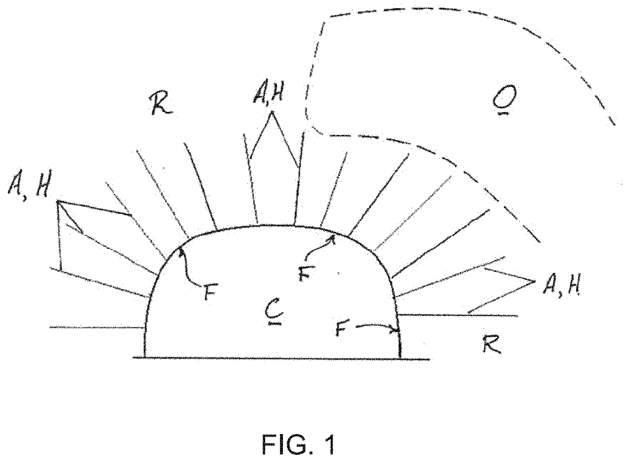
[0068]Referring firstly to FIG. 1 of the drawings, a cross-sectional view of a mine environment is illustrated schematically. An excavated cavity or chamber C of the mine is shown in a cross-section taken normal or transverse to a length of that cavity or chamber C into the page. The cavity C is essentially surrounded by rock strata R and an ore deposit O above and displaced into the page from the cavity C can also be seen. The cavity C has been excavated to provide access for workers and equipment into the vicinity of the ore body O. Where the rock strata R surrounding the cavity C is unstable and liable to rock-fall or even partial collapse, rock anchors A can be employed to stabilise the rock strata R to render the underground environment safe for personnel and equipment. To this end, the rock anchors A are set in holes H that are drilled from the cavity C from an outer rock face F into the rock strata R. The holes H drilled and the rock anchors themselves are typically in the ra...


PUM


Abstract

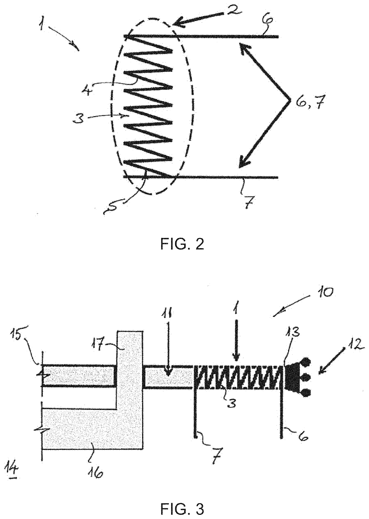
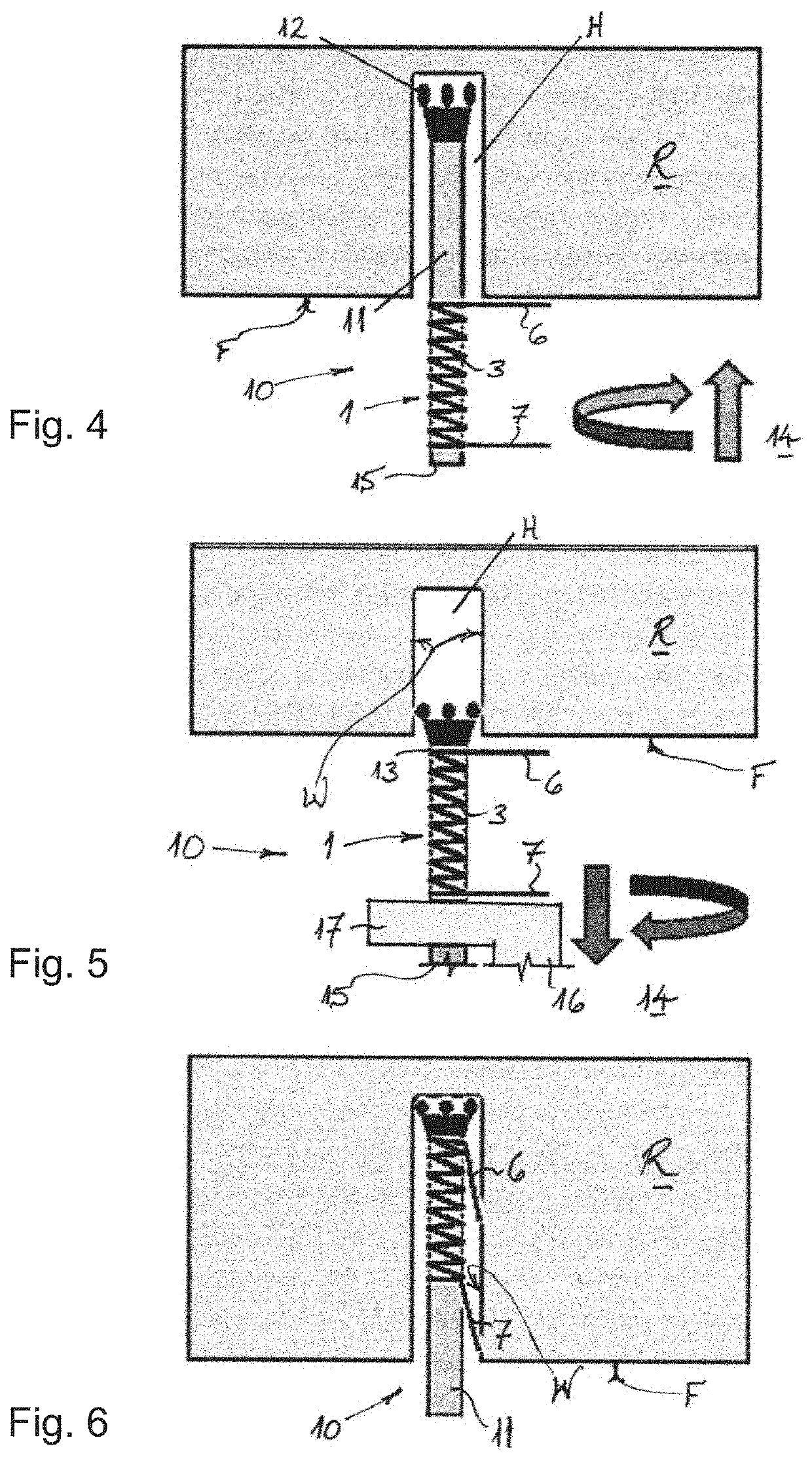
The present invention provides a retainer device 1 for retaining or holding an anchor rod 11 of a rock anchor, especially a self-drilling anchor, in a hole H drilled above horizontal. The retainer device 1 comprises: a body portion 2 configured to be mounted on the anchor rod 11, and especially on an outer or external periphery of the anchor rod, and at least one locking arm or tab 6, 7 that projects from the body portion 2 in a direction transverse to a longitudinal extent of the anchor rod 11. The body portion 2 is configured for movement relative to the anchor rod 11 in use, and the at least one arm or tab 6, 7 is configured to deform so as to engage and bear against an inner wall W of the hole H when the retainer device 1 mounted on the anchor rod 11 is driven into the hole H. The invention also relates to a rock anchor system 10, comprising: at least one elongate anchor rod 11; a drill bit 12 configured for attachment to one end region 13 of the elongate anchor rod 11 for drilling the anchor rod 11 into rock strata R; and at least one retainer device 1 according to the invention described above for retaining or holding the anchor rod 11 in a hole H drilled in the rock strata R above horizontal. The invention also provides a method for installing a rock anchor.

Description

FIELD OF THE INVENTION[0001]The present invention relates to a retainer device for a rock anchor, and particularly for retaining or holding an anchor rod of a rock anchor in a rock bore drilled above horizontal during installation. The present invention also relates to a rock anchor system including such a retainer device and a method of installing a rock anchor.[0002]Thus, it will be appreciated that the present invention has particular application or use in the mining industry, and it will be convenient to describe the invention herein in that exemplary context. It will be noted, however, that applications may also be contemplated in other fields, such as in the construction industry.BACKGROUND OF THE INVENTION[0003]In underground mine environments, a body or vein of ore will typically be accessed by excavating cavities into the rock strata below the ore body or vein and then working towards the ore deposit from below. This technique is referred to in the mining field as “overhand...

Claims


Application Information

Patent Timeline
IPC IPC(8): E21D21/00
CPCE21D21/0093E21D21/0046E21D21/0053E21D21/008
Inventor THOMAS, SAMNOONAN, GERRY
Owner JUSAND NOMINEES PTY LTD
Learn More