
Split front end for flexible back end cluster processing

a back end cluster and split technology, applied in the field of split front end for flexible back end cluster processing, can solve the problems of slowing down development progress, software that is developed on the local development system is not guaranteed to execute correctly on the remote system,

Active Publication Date: 2020-03-05
DATABRICKS INC
View PDF23 Cites 32 Cited by
  • Summary
  • Abstract
  • Description
  • Claims
  • Application Information

AI Technical Summary

Benefits of technology

The invention is a system for code development and execution that allows developers to develop software on a local system and have it executed on a remote system, such as a cluster system. The system prepares the code for execution on the remote system by parsing it to determine data items and metadata about the data items, and creating a logical plan based on this metadata. This helps ensure that the code runs correctly on the remote system. The invention also allows developers to use a local development system and have it executed on the remote system, but this requires extra development effort and slows down development progress. Overall, the invention improves efficiency and flexibility in code development and execution.

Problems solved by technology

Software that is developed on the local development system is not guaranteed to execute correctly on the remote system for cluster processing.
In the event that the developer wishes to develop code on the local development system (e.g., because it has customizations preferred by the developer, because it is local and more responsive, because has development software preferred by the developer, etc.) but execute the code on the cluster system (e.g., because it is more powerful than the local development system, because it contains a data set not otherwise accessible to the developer, etc.), a problem is created wherein extra development effort is required of the developer, slowing down development progress.

Method used

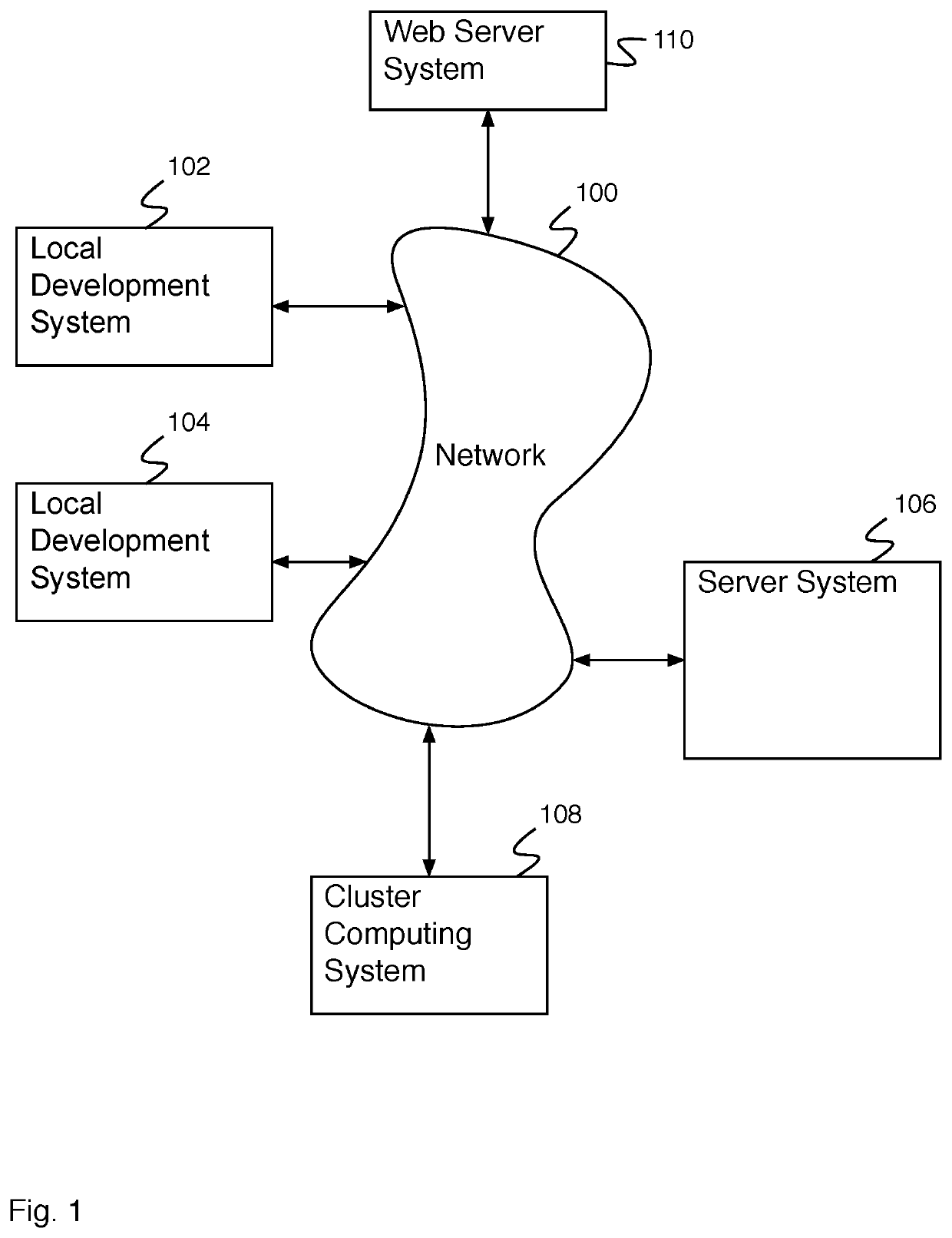
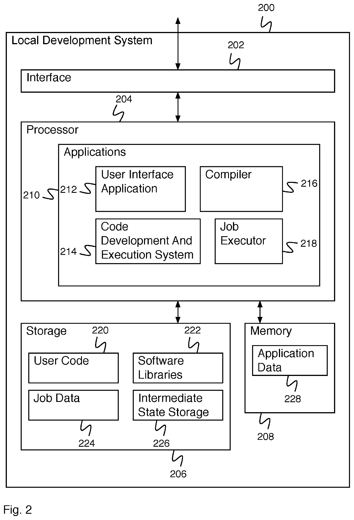
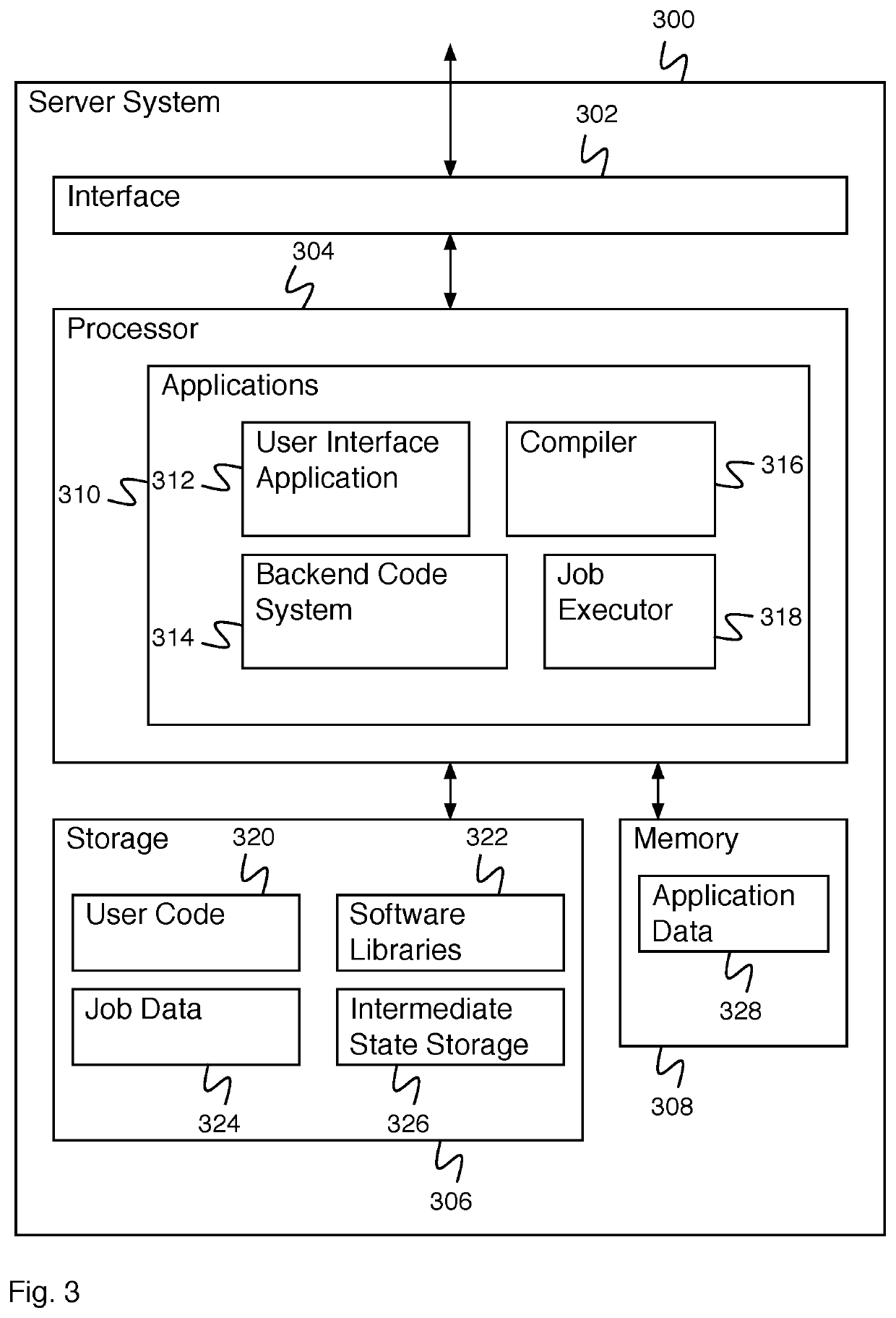

Image

  • Split front end for flexible back end cluster processing
  • Split front end for flexible back end cluster processing
  • Split front end for flexible back end cluster processing

Examples


Embodiment Construction

[0011]The invention can be implemented in numerous ways, including as a process; an apparatus; a system; a composition of matter; a computer program product embodied on a computer readable storage medium; and / or a processor, such as a processor configured to execute instructions stored on and / or provided by a memory coupled to the processor. In this specification, these implementations, or any other form that the invention may take, may be referred to as techniques. In general, the order of the steps of disclosed processes may be altered within the scope of the invention. Unless stated otherwise, a component such as a processor or a memory described as being configured to perform a task may be implemented as a general component that is temporarily configured to perform the task at a given time or a specific component that is manufactured to perform the task. As used herein, the term ‘processor’ refers to one or more devices, circuits, and / or processing cores configured to process da...


PUM


Abstract

A system for code development and execution includes a client interface and a client processor. The client interface is configured to receive user code for execution and receive an indication of a server that will perform the execution. The client processor is configured to parse the user code to identify one or more data items referred to during the execution. The client processor is also configured to provide the server with an inquiry for metadata regarding the one or more data items, receive the metadata regarding the one or more data items, determine a logical plan based at least in part on the metadata regarding the one or more data items; and provide the logical plan to the server for execution.

Description

BACKGROUND OF THE INVENTION[0001]Typically, compiled software code is created by a developer and then is executed by a processing system, which these days is often a cluster processing systems. For a cluster processing system, the developer develops (e.g., writes, tests, debugs, etc.) the software using a development environment running on the system for cluster processing, compiles the software on the system for cluster processing, and executes the software on the system for cluster processing. In the event that the user desires to develop software using a local development system, they develop the software on the local development system, compile the software on the local development system, and execute the software on the local development system. Software that is developed on the local development system is not guaranteed to execute correctly on the remote system for cluster processing. In the event that the developer wishes to develop code on the local development system (e.g.,...

Claims


Application Information

Patent Timeline
IPC IPC(8): G06F8/41G06F8/54G06F8/70G06F11/36G06F11/07G06F17/30G06F21/62
CPCG06F8/47G06F16/23G06F16/907G06F11/0757G06F2221/2141G06F21/62G06F11/0706G06F8/54G06F8/427G06F11/3664G06F2201/865G06F8/70G06F8/20G06F11/1482G06F11/1497
Inventor SHANKAR, SRINATHLIANG, ERIC KENG-HAOOWEN, GREGORY GEORGE
Owner DATABRICKS INC
Learn More