Saturation prevention of current transformer

Active Publication Date: 2020-03-19
ANALOG DEVICES GLOBAL UNLTD
View PDF7 Cites 4 Cited by
  • Summary
  • Abstract
  • Description
  • Claims
  • Application Information

AI Technical Summary

Benefits of technology

[0005]According to an embodiment of the present disclosure, method of preventing saturation of a current transformer. The method includes sensing alternating current (AC) current on an input line. The method includes converting the sensed AC current into direct current (DC) current to drive a load based on the DC current. The method includes controlling a flow of the DC current from the current transformer to the load based on a control signal. The method includes providing a feedback signal based on a voltage representative to the flow of the DC current to the load. The method includes causing a power switch circuit to turn on with the control signal when a magnitude of the feedback signal exceeds a threshold magnitude. The method includes supplying a pulse width modulation (PWM) signal to cause the control signal to be provided substantially symmetrical to the power switch circuit. The method includes causing the power switch circuit to turn on with the control signal at a rate based on a frequency of the PWM signal to reduce an imbalance of the load during one or more cycles of the AC current, wherein the frequency of the PWM signal is greater than that of the feedback signal.
[0006]According to an embodiment of the present d

Problems solved by technology

When the current transformer is used as a shunt-boost based power supply, as the load of the CT is unsymmetrical during a whole AC cycle due to

Method used


Image

  • Saturation prevention of current transformer
  • Saturation prevention of current transformer
  • Saturation prevention of current transformer

Examples


Embodiment Construction

[0015]The detailed description set forth below is intended as a description of various configurations of the subject technology and is not intended to represent the only configurations in which the subject technology may be practiced. The appended drawings are incorporated herein and constitute a part of the detailed description. The detailed description includes specific details for the purpose of providing a thorough understanding of the subject technology. However, the subject technology is not limited to the specific details set forth herein and may be practiced using one or more implementations. In one or more instances, structures and components are shown in block diagram form in order to avoid obscuring the concepts of the subject technology.

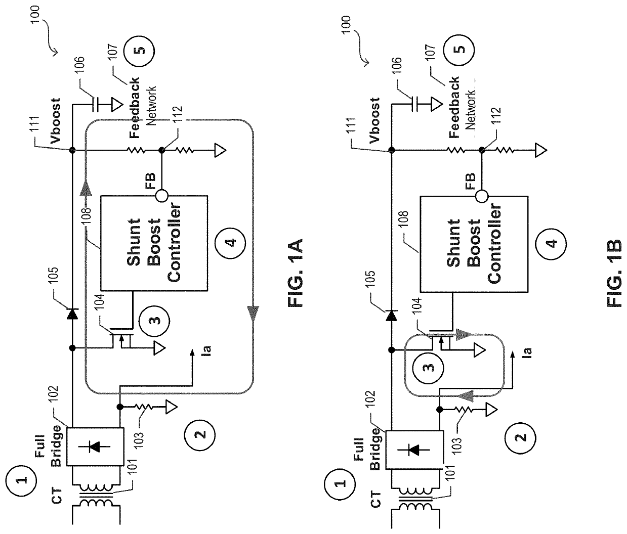
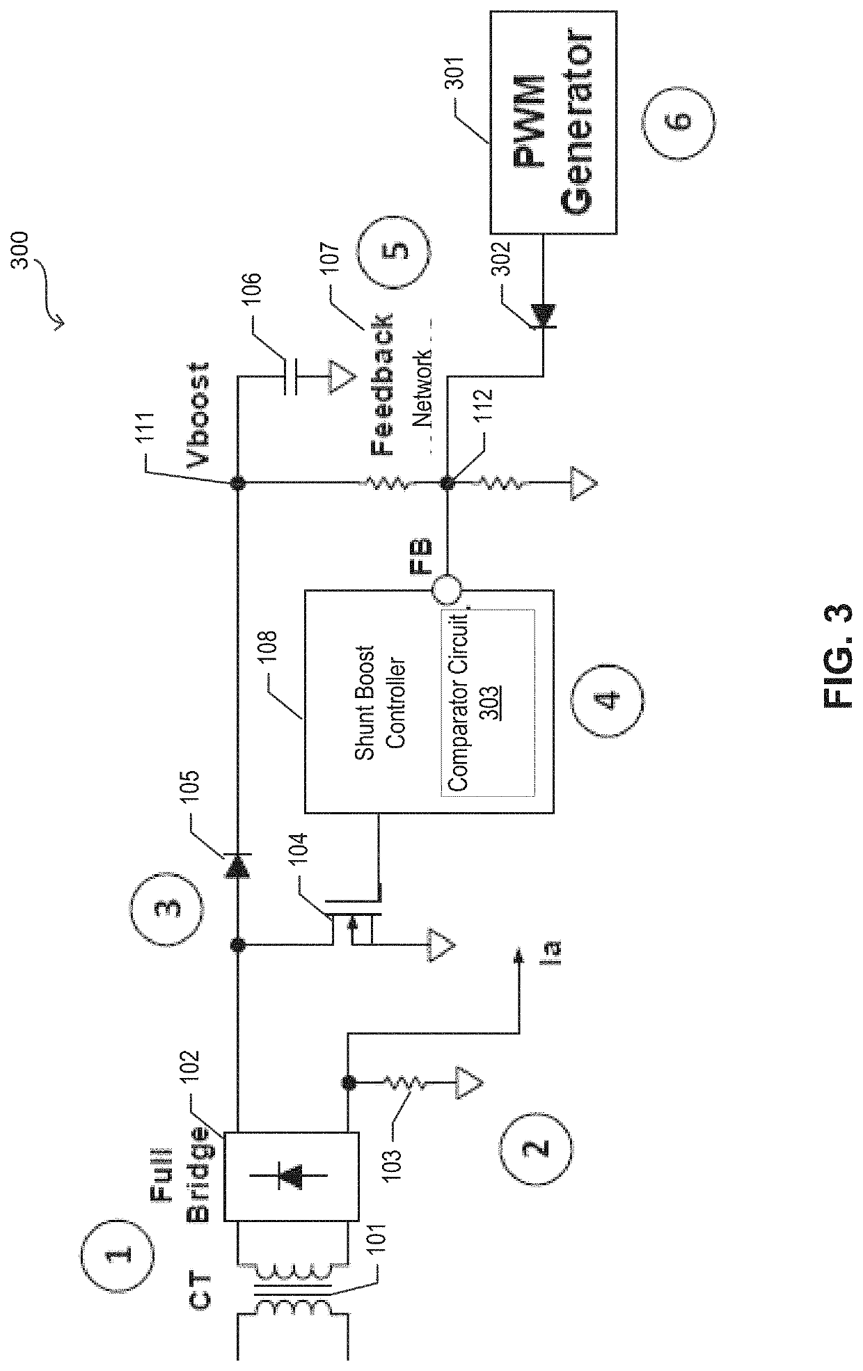
[0016]The subject technology uses additional pulse width modulation (PWM) signaling to influence the closed loop of a shunt boost controller and reduces the imbalance of a load in an AC cycle. Therefore, the remanence of the current trans...


PUM


Abstract

The subject disclosure provides for utilizing pulse width modulation (PWM) signaling to influence a closed loop of a shunt boost controller and reduce an imbalance of a load. The imbalance reduction helps reduce remanence of a current transformer (CT) and thereby prevent saturation of the CT. A shunt boost controller provides the control signal to control flow of current to the load. A feedback network provides a feedback signal to the shunt boost controller based on a direct current (DC) voltage and causes a power switch circuit to turn on when a magnitude of the feedback signal exceeds a threshold magnitude. The PWM generator supplies a PWM signal to cause the control signal to be provided more symmetrical to the power switch circuit and causes the power switch circuit to turn on more frequently with the control signal to reduce the imbalance of the load.

Description

FIELD OF THE DISCLOSURE[0001]The present description relates generally to power converter systems, and more particularly, to saturation prevention of current transformer.BACKGROUND[0002]In module case circuit breaker (MCCB) applications, a current transformer (CT) is used as a shunt boost power supply as well as used to provide the alternating current (AC) information. When the current transformer is used as a shunt-boost based power supply, as the load of the CT is unsymmetrical during a whole AC cycle due to the shunt boost topology, there will be remanence in the current transformer under a certain load condition and causes the CT into saturation. Because the CT also provides the sensed current information in a MCCB application, when saturation happens, the accuracy and linearity of the sensed current signal is influenced.SUMMARY OF THE DISCLOSURE[0003]The subject disclosure provides for utilizing pulse width modulation (PWM) signaling to influence a closed loop of a shunt boost ...

Claims


Application Information

Patent Timeline
IPC IPC(8): H01F27/40H02M1/40H02M7/06H02M3/335
CPCH02M3/335H01F27/402H02M1/40H02M7/068H02M7/217H02M1/0038H02M1/0009H02M1/0012H02M7/06H02M5/12H02M3/156H01F38/32H02M1/0064H02M1/007
Inventor YANG, LIUQINGYE, JIANZHU, ZHIJIE
Owner ANALOG DEVICES GLOBAL UNLTD
Why Eureka
Try Eureka