Wireless temperature probe

a temperature probe and wireless technology, applied in the field of wireless temperature probes, can solve the problems of difficult cleaning and storage, other user problems, difficult use of the temperature probe, etc., and achieve the effects of reducing the accuracy, good measurement, and limited heat resistance of the battery

Pending Publication Date: 2020-03-26
MASTRAD
View PDF10 Cites 13 Cited by
  • Summary
  • Abstract
  • Description
  • Claims
  • Application Information

AI Technical Summary

Benefits of technology

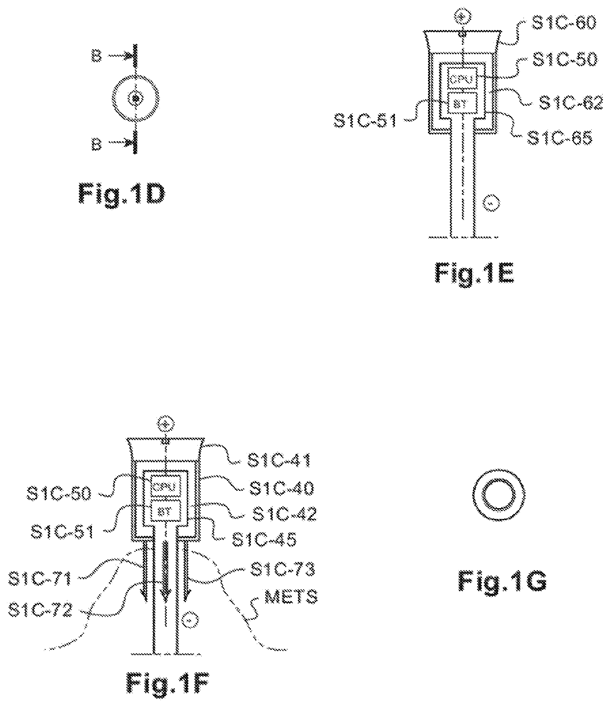
[0011]In the thermometer probe S1 (as generally shown in FIGS. 3A-3E), another temperature sensor, of for example, the thermistor or RTD (Resistance Temperature Detector) or thermocouple, may be added, said sensor being placed beside the electromagnetic wave emitter in the interior of the end fitting (S1C-52), (also referenced T3′ below). Placing the sensor inside the end fitting with direct contact to the inner part of the end fitting but not in contact with the outside environment, protects such sensor from overheating during high heat or long cooking and including flare up with flames above a temperature of 500° C.
[0012]Measuring the internal temperature of the end fitting allows the user to sense indirectly variations of the outside ambient conditions without direct contact with high heat or with direct flare up (>500° C.). This also allows the use of a thermistor sensor, efficient enough instead of using a thermocouple or a RTD sensor, much more

Problems solved by technology

Such thermometers are not easy to use with container-and-cover assemblies in the closed state.
Such cables create other user issues including tangling, overheating, difficulty cle

Method used


Image

  • Wireless temperature probe
  • Wireless temperature probe
  • Wireless temperature probe

Examples


Embodiment Construction

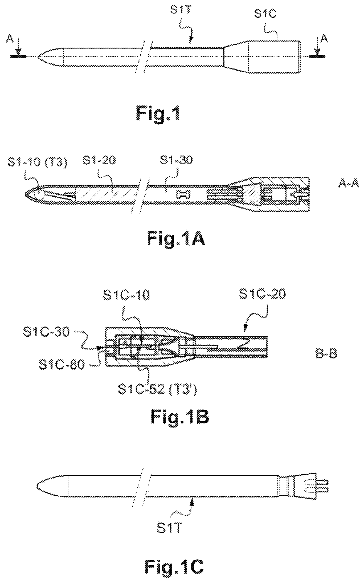
[0067]As noted above, the embodiments described herein are generally directed to methods and systems for aiding with the control of cooking. In one embodiment, the system includes a thermometer probe that includes an emitter, a battery power supply, and a thermally conductive shaft with at least one temperature sensor. The thermally conductive shaft is positioned in the interior of a heated milieu (e.g. a food item). The thermally conductive shaft includes a tip at a first end, and an end fitting at a second end. The battery and controller unit are positioned in the thermally conductive shaft, along with the temperature sensor, which is in thermal contact with the thermally conductive shaft. The end fitting is hollow such that the end fitting houses the emitter and a second temperature sensor.

[0068]In another embodiment, a method is provided for computing a temperature variation speed inside an end fitting from a temperature difference inside the end fitting. The method includes ini...


PUM


Abstract

Embodiments are directed to a system for aiding with the control of cooking. The system includes a thermometer probe that has an emitter, a controller unit or CPU, a battery power supply, and a thermally conductive shaft with a temperature sensor. The thermally conductive shaft is positioned in the interior of a heated milieu (e.g. a food item). The thermally conductive shaft includes a tip at a first end, and an end fitting at a second end. The battery and controller unit are positioned in the thermally conductive shaft, along with the temperature sensor, which is in thermal contact with the thermally conductive shaft. The end fitting is hollow such that the end fitting houses the emitter and a second temperature sensor. Other embodiments are directed to a method for computing a temperature variation speed from a temperature difference inside the end fitting.

Description

CROSS-REFERENCE TO RELATED APPLICATIONS[0001]This application claims priority to PCT Application PCT / FR2017 / 051935, filed on Jul. 13, 2017, which application claims priority to French application FR 16 / 56800, filed on Jul. 14, 2016. This application further claims priority to and the benefit of U.S. Provisional Patent Application No. 62 / 547,003, filed Aug. 17, 2017, entitled “Improvement of Thermometer Probes for Cooking,” and U.S. Provisional Patent Application No. 62 / 574,114, filed Oct. 18, 2017, entitled “Thermometer Probes for Cooking,” both of which applications are incorporated by reference herein in their entirety.BACKGROUND[0002]Most of the time, users need to know what is happening during cooking, particularly in terms of temperature. Thermometers, or temperature probes, intended to be sunk into foodstuffs during cooking in order to monitor the internal temperature thereof are generally known. Such thermometers are not easy to use with container-and-cover assemblies in the ...

Claims


Application Information

Patent Timeline
IPC IPC(8): G01K1/02G01K1/12
CPCG01K2207/06G01K1/12G01K1/024G01K2215/00G01K3/10
Inventor LION, MATHIEUPICCHI, MATHIEULION, JONATHAN
Owner MASTRAD
Why Eureka
Try Eureka