Power supply device, vehicle equipped with same, and electricity storage device

Pending Publication Date: 2020-03-26
SANYO ELECTRIC CO LTD
View PDF1 Cites 3 Cited by
  • Summary
  • Abstract
  • Description
  • Claims
  • Application Information

AI Technical Summary

Benefits of technology

[0008]A power supply device according to a first aspect of the present invention includes a battery stack body that includes a plurality of secondary battery cells that are stacked, a pair of end plates disposed on both end surfaces of the battery stack body, respectively, and binding bars that are disposed on side surfaces of the battery stack body, respectively, and bind the pair of end plates. Each of the binding bars includes engaging steps that are opposite the pair of end plates, respectively. Each of the engaging steps extends in a direction intersecting with a stack direction of the battery stack body. Each of the pair of end plates includes engaging protrusions that are opposite the binding bars, respectively. The engaging protrusions engage with the engaging steps. The above configuration increases rigidity that binds the battery stack body together. Further, a material and a thickness of the binding bars are not changed.
[0009]In a power supply device according to a second aspect of the present invention that includes the above configuration, each of the binding bars may include a pair of reinforcing members that are on a binding bar main surface that is opposite the battery stack body, and the pair of reinforcing members may protrude toward the mating end plates, and may include the respective engaging steps that engage with the engaging protrusions. According to the above configuration, a thickness of edges of the binding bars is easily ensured. The thickness allows the engaging steps to be formed. Further, a thickness of the binding bars themselves is not thick. Therefore, a manufacturing cost decreases.
[0010]In a power supply device according to a third aspect of the present invention that includes any one of the above configurations, each of the binding bars may include a metal plate and a pair of metal blocks, and each of the pair of metal blocks has a dimension in the direction intersecting with the stack direction of the battery stack body that is larger than a dimension of the metal plate in the direction intersecting with the stack direction of the battery stack body, and the pair of metal blocks may be the pair of rein

Problems solved by technology

However, a large thickness of the binding bars increases a weight o

Method used


Image

  • Power supply device, vehicle equipped with same, and electricity storage device
  • Power supply device, vehicle equipped with same, and electricity storage device
  • Power supply device, vehicle equipped with same, and electricity storage device

Examples


Example

First Exemplary Embodiment

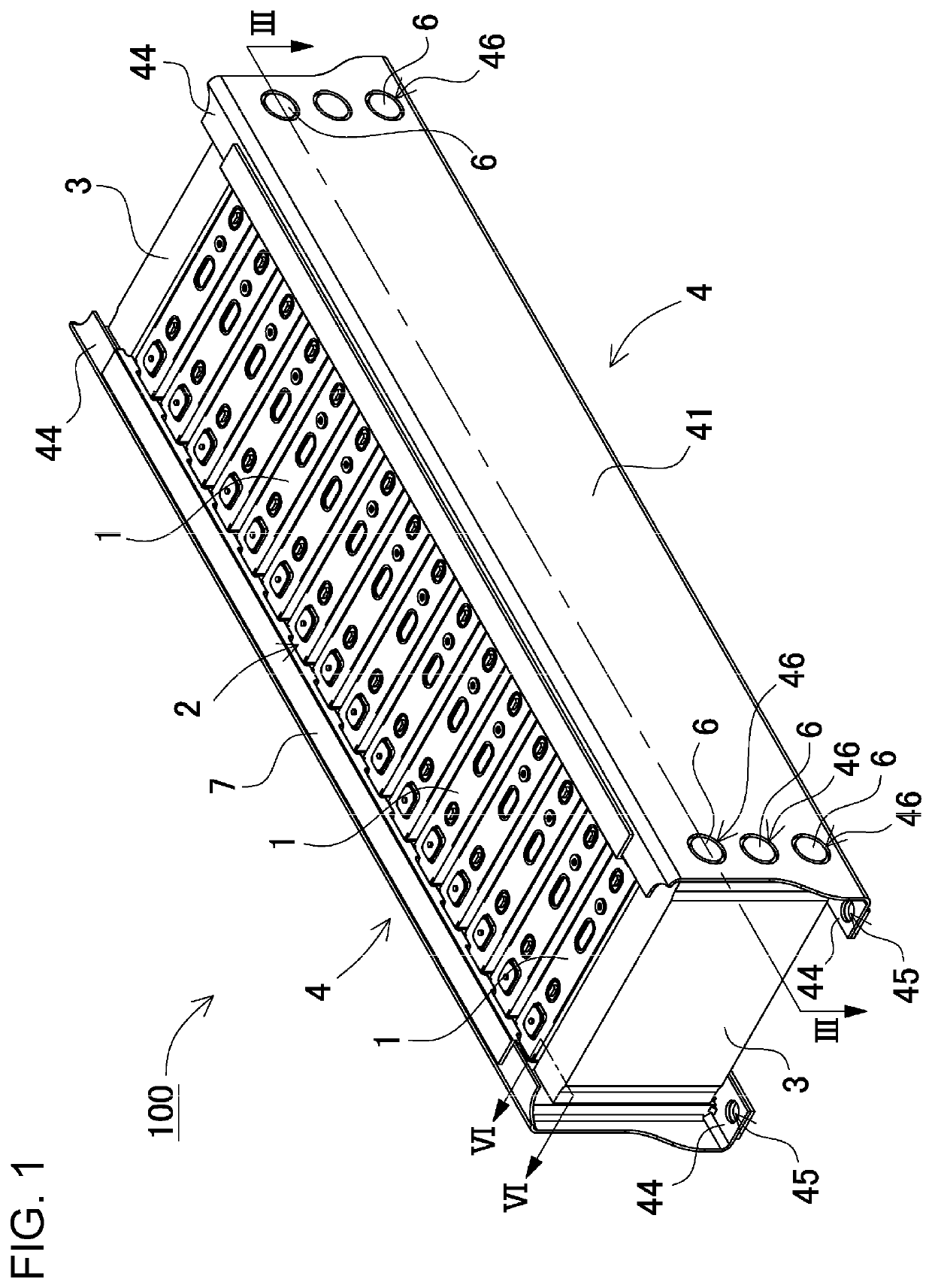
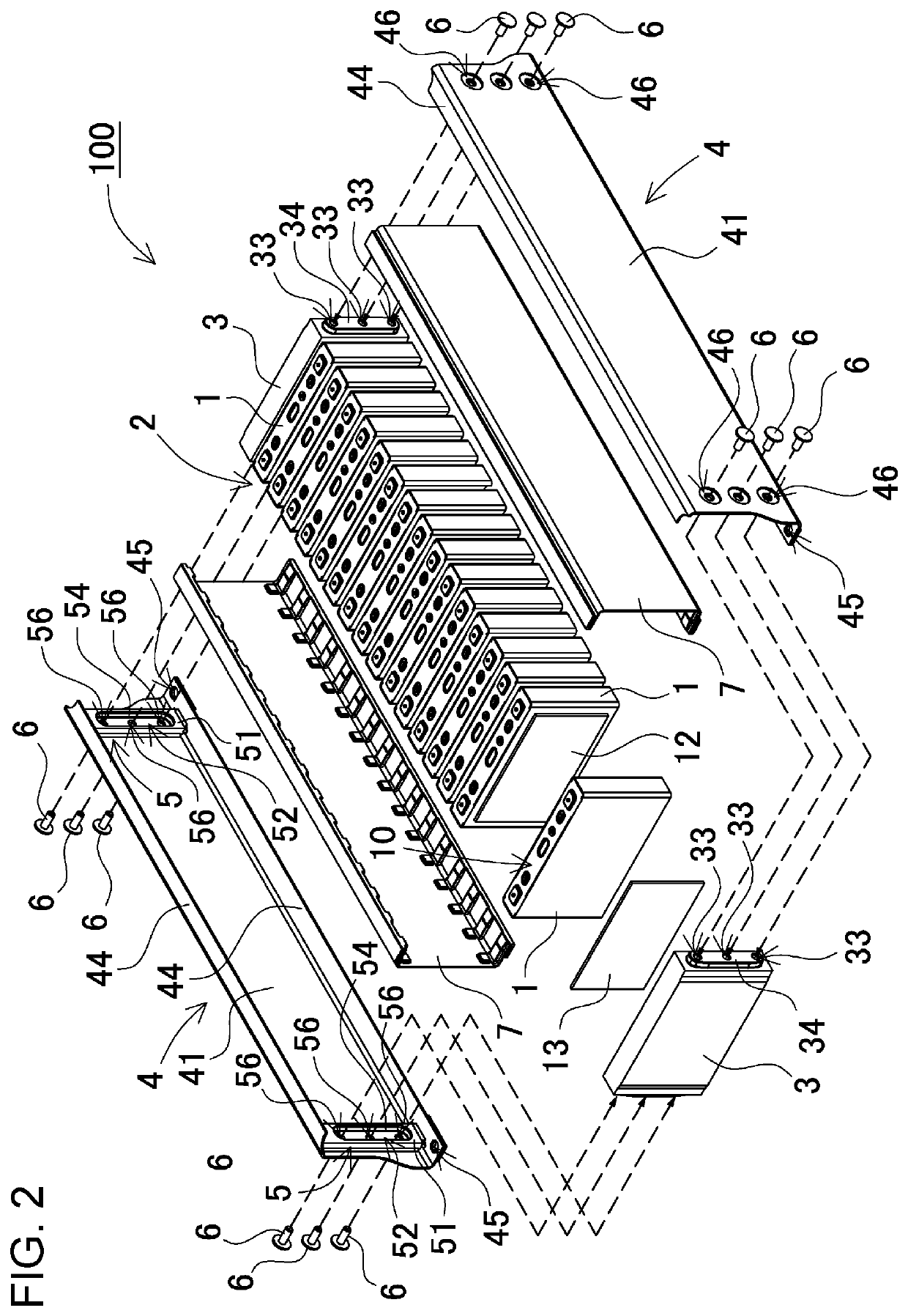
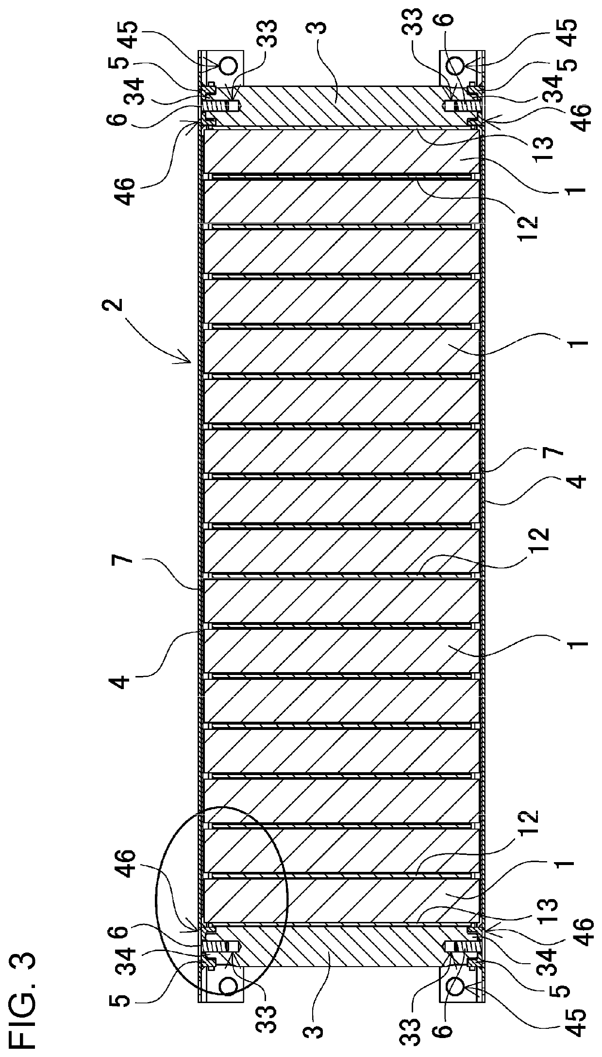
[0037]FIG. 1 is a perspective view that illustrates power supply device 100 according to a first exemplary embodiment of the present invention. FIG. 2 is an exploded perspective view that illustrates power supply device 100 according to the first exemplary embodiment of the present invention. Power supply device 100 illustrated in FIGS. 1 and 2 includes battery stack body 2 that includes a plurality of secondary battery cells 1 that are stacked, a pair of end plates 3 disposed at both ends of battery stack body 2, and a pair of binding bars 4 that bind battery stack body 2. Both ends of binding bars 4 are connected with the pair of end plates 3. Reinforcing member 5 is interposed between each of end plates 3 and each of binding bars 4. As illustrated in FIGS. 1 and 2, insulating sheet 7 may be interposed between each of binding bars 4 and the battery stack body.

(Secondary Battery Cell 1)

[0038]As illustrated in FIG. 2, secondary battery cells 1 are each a re...


PUM


Abstract

A power supply device includes: a battery stack body that includes a plurality of secondary battery cells that are stacked; a pair of end plates disposed on both end surfaces of the battery stack body, respectively; and binding bars that are disposed on both the end surfaces of the battery stack body, respectively, and bind the pair of end plates. Each of the binding bars includes engaging steps that are opposite the pair of end plates, respectively. Each of the engaging steps extends in a direction intersecting with a stack direction of the battery stack body. Each of the pair of end plates includes engaging protrusions that are opposite the binding bars, respectively. The engaging protrusions engage with engaging steps. Consequently, rigidity that binds the battery stack body together is increased without changing a material and a thickness of the binding bars.

Description

TECHNICAL FIELD[0001]The present invention relates to a power supply device, and a vehicle and an electricity storage device that are equipped with the power supply device.BACKGROUND ART[0002]A power supply device that includes many secondary batteries connected with each other in series or in parallel is used to drive a vehicle, for example. FIG. 13 is an exploded perspective view that illustrates an example of such a power supply device. Power supply device 900 illustrated in FIG. 13 includes a plurality of secondary battery cells 901 and a plurality of spacers 902 that are alternately stacked. Secondary battery cells 901 are rectangular (prismatic). Power supply device 900 includes end plates 903 disposed on end surfaces, respectively, and binding bars 904 that bind secondary battery cells 901, spacers 902, and end plates 903 together. Spacers 902 are made of a hard resin.[0003]It is known that secondary battery cells become swollen by being charged and discharged. Especially bec...

Claims


Application Information

Patent Timeline
IPC IPC(8): H01M2/10B60K6/28H01M10/46H01M50/103H01M50/209H01M50/264H01M50/289
CPCH01M2/1077B60K6/28H01M10/46H01M2220/20H01M10/0413H01M10/0486Y02T10/7072Y02T90/12H01M50/209H01M50/264H01M50/289H01M50/103Y02E60/10
Inventor ISHIBASHI, KENGOMITSUBORI, SHINICHTERAUCHI, SHINOBU
Owner SANYO ELECTRIC CO LTD
Why Eureka
Try Eureka