Reducing resonant noise in seismic data acquired using a distributed acoustic sensing system

Active Publication Date: 2020-04-02
HALLIBURTON ENERGY SERVICES INC
View PDF2 Cites 15 Cited by
  • Summary
  • Abstract
  • Description
  • Claims
  • Application Information

AI Technical Summary

Problems solved by technology

In some cases, the seismic data might include undesirable resonant noise artifacts such as ringing.
The undes

Method used


Image

  • Reducing resonant noise in seismic data acquired using a distributed acoustic sensing system
  • Reducing resonant noise in seismic data acquired using a distributed acoustic sensing system
  • Reducing resonant noise in seismic data acquired using a distributed acoustic sensing system

Examples


Embodiment Construction

[0085]Example embodiments include the following:

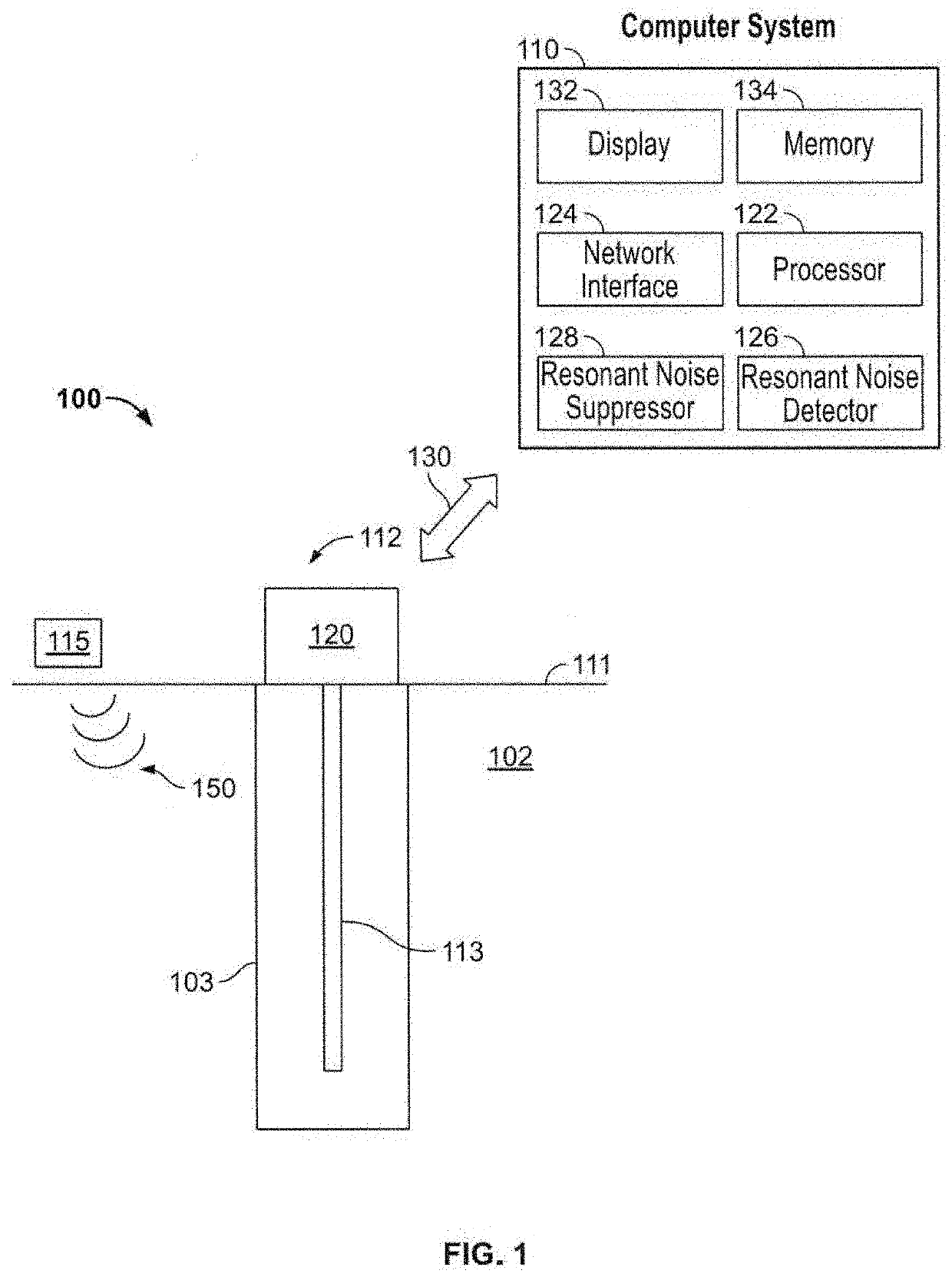
[0086]Embodiment 1 is a method, the method comprising: positioning a distributed acoustic sensor within a wellbore of a geologic formation; detecting, using the distributed acoustic sensor, seismic waves; generating a raw seismic profile of seismic data based on the detected seismic waves; detecting resonant noise in the seismic data; reducing the resonant noise in the seismic data; and outputting a resonant noise reduced raw seismic profile based on the reduction of the resonant noise in the seismic data. Reducing the resonant noise as described in any of the preceding embodiments comprises: transforming the seismic data from a time domain into a frequency domain, wherein transformed seismic data indicates a frequency spectrum of the seismic data; determining amplitudes of frequencies in the frequency spectrum which exceeds a threshold level; identifying the seismic data in the raw seismic profile which correspond to the amplitudes of...


PUM


Abstract

A distributed acoustic sensor is positioned within a wellbore of a geologic formation. Seismic waves are detected using the distributed acoustic sensor. A raw seismic profile is generated based on the detected seismic waves. Resonant noise is identified and reduced in seismic data associated with the raw seismic profile.

Description

RELATED DISCLOSURE[0001]This disclosure claims the benefit of priority under 35 U.S.C. § 119(e) of U.S. Provisional Application No. 62 / 738,761, filed Sep. 28, 2018 entitled “Resonant Noise Reduction for Distributed Acoustic Sensing Data”, the contents of which are herein incorporated by reference in its entirety.FIELD OF USE[0002]This disclosure generally relates to a distributed acoustic sensing (DAS) system associated with seismic monitoring of a geologic formation, and more particularly to reducing resonant noise in seismic data acquired using the DAS system.BACKGROUND[0003]A number of different operations are used to extract hydrocarbons from a geologic formation which include drilling a wellbore through and / or into the geologic formation at a desired well site, fracturing the wellbore, and pumping the hydrocarbons which flow into the wellbore to the surface of the geologic formation. Some or all of these operations are conducted based on seismic monitoring of the geologic forma...

Claims


Application Information

Patent Timeline
IPC IPC(8): E21B49/00G01V1/36G01V1/32
CPCE21B49/00G01V1/366G01V1/32G01V1/226G01V1/42G01V2210/32G01V2210/161G01V2210/20G01V1/36G01V1/37
Inventor WILLIS, MARK ELLIOTTBARRIOS LOPEZ, OSCAR AUGUSTOPALACIOS, PEDRO WILLIAMCHENG, DONGJIE
Owner HALLIBURTON ENERGY SERVICES INC
Why Eureka
Try Eureka