Non-intrusive workflow assessment (NIWA) for manufacturing optimization

Active Publication Date: 2020-04-02
RGT UNIV OF CALIFORNIA
View PDF0 Cites 5 Cited by
  • Summary
  • Abstract
  • Description
  • Claims
  • Application Information

AI Technical Summary

Benefits of technology

[0007]It is an objective of the present invention to provide a low-cost solution to help in monitoring machines and workflow from a perspective of efficiency, efficiency, as specified in the in

Problems solved by technology

Equipment and machine prognosis and operational health monitoring have long been an issue against energy and production efficiency in small and medium factories around the country.
Small and medium factories have comparably low automated level and mach

Method used


Image

  • Non-intrusive workflow assessment (NIWA) for manufacturing optimization
  • Non-intrusive workflow assessment (NIWA) for manufacturing optimization
  • Non-intrusive workflow assessment (NIWA) for manufacturing optimization

Examples


example

[0041]The following is a non-limiting example of the present invention. It is to be understood that said example is not intended to limit the present invention in any way. Equivalents or substitutes are within the scope of the present invention.

[0042]A small factory in California is implementing the present invention. On a Sunday when there are no workers in the factory, calibration procedures are performed to obtain the machine profile of 5 machines. Infrared cameras are installed and the temperature profiles of 5 machines are collected in their ON state, OFF state, and STAND-BY. The energy consumption of each machine is also calculated in its ON state, OFF state, and STAND-BY. The temperature profiles and energy consumption of the machines make up the machine profile. On Monday, when the workers are in the factory, a video camera focused on each machine captures images of the workers' interactions with the machines. The smart utility meter measures the aggregate energy consumption...


PUM


Abstract

Non-intrusive monitoring and workflow assessment to optimize manufacturing environments are described herein. The systems and method combines computer vision and energy load disaggregation to track worker activity and equipment usage and status. These events are then correlated to optimize workflows and energy efficiency.

Description

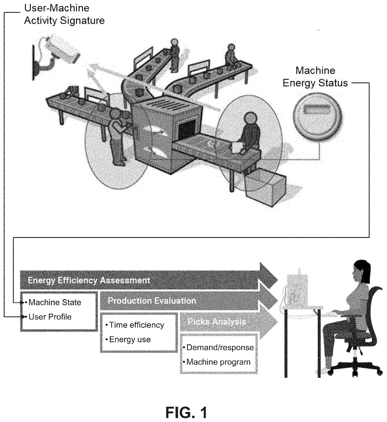
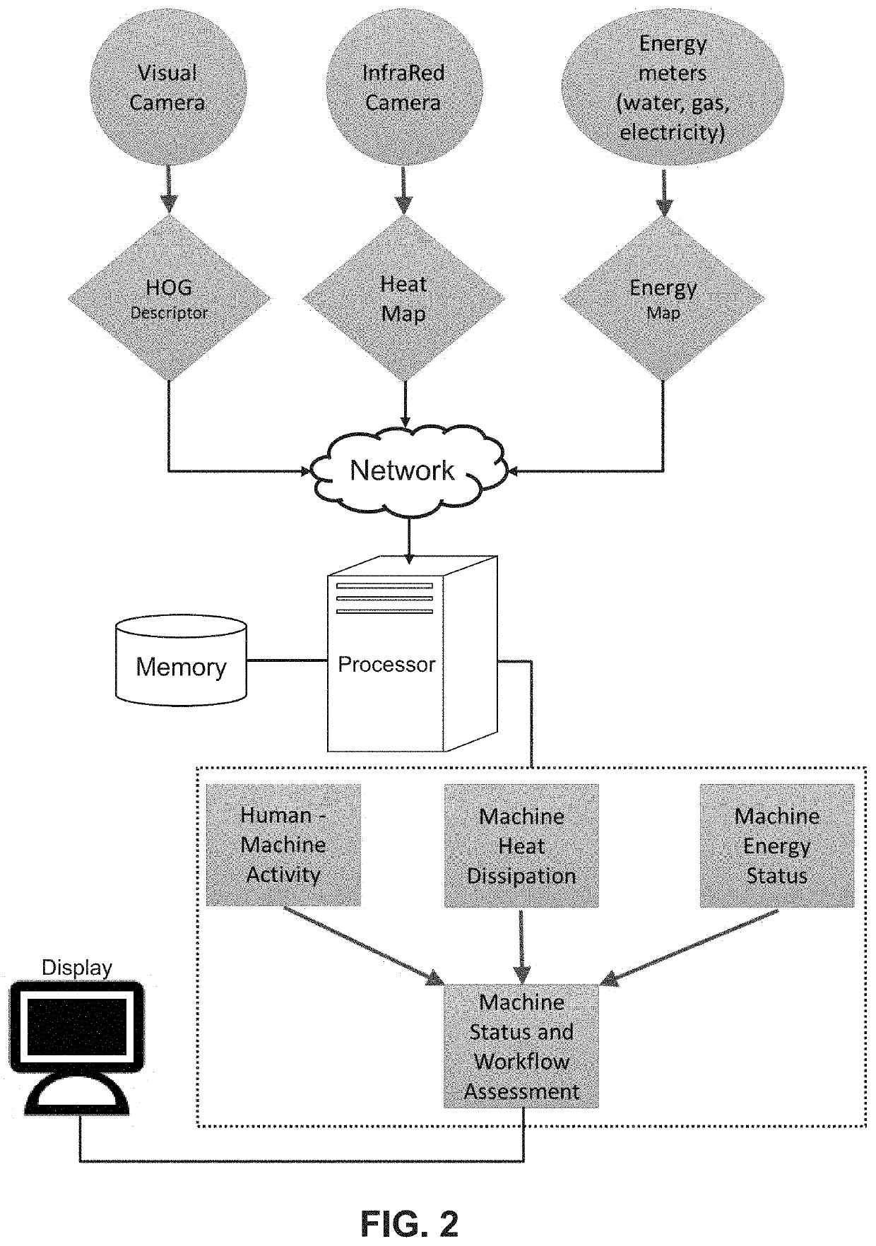
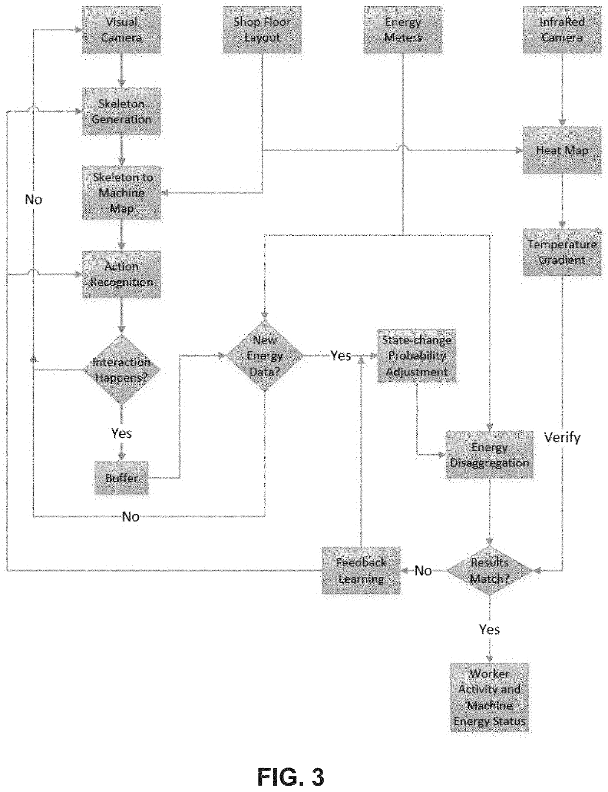
CROSS-REFERENCES TO RELATED APPLICATIONS[0001]This application is a non-provisional and claims benefit of U.S. Provisional Application No. 62 / 738,396 filed Sep. 28, 2018, the specification(s) of which is / are incorporated herein in their entirety by reference.FIELD OF THE INVENTION[0002]The present invention relates to a platform for workflow assessment by non-intrusive monitoring combining computer vision and energy load disaggregation.BACKGROUND OF THE INVENTION[0003]Equipment and machine prognosis and operational health monitoring have long been an issue against energy and production efficiency in small and medium factories around the country. These inefficiencies are highly impacted by workers' skills and workflow within the already established manufacturing processes. Small and medium factories have comparably low automated level and machines are less well-maintained as compared to bigger factories. Traditional solutions for this problem usually require the installation of sever...

Claims


Application Information

Patent Timeline
IPC IPC(8): G06Q10/06G06Q50/06
CPCG06Q10/06398G06Q50/06G06Q50/04G05B23/0216G01R22/10
Inventor LI, GUANN-PYNGKLOPFER, MICHAEL JOHNGAGO-MASAGUE, SERGIODONOVAN, RICHARD P.REN, YUTIAN
Owner RGT UNIV OF CALIFORNIA
Why Eureka
Try Eureka