
Eureka
For R&D, Eureka makes reading and utilizing patents & technical documents easy.
Eureka AIR
Designed for self-driven R&D workflows. Generate viable solutions, solve complex R&D challenges, empower your innovation with AI.

Eureka Materials
Designed for material experts only. Revolutionize your material R&D, from search, analyze, to developing new materials.

TechResearch
Generate reliable direction feasibility study reports for your R&D in just a few steps.

TechSeek
Discover and master advanced knowledge NOW. Basics, ideas, possibilities, all at once.

TechMind
As an expert in R&D Theories, TechMind can generates customized viable solutions instantly.

TechRisk
Analyze your overall solution with one click, know your potential R&D risks in advance.

TechMonitor
Get weekly tech updates, stay abreast of the latest tech innovations and key insights.
New packing for improving contact between a gas phase and a dispersed solid phase moving in counter-current flow
- Summary
- Abstract
- Description
- Claims
- Application Information
AI Technical Summary
Benefits of technology
Problems solved by technology
Method used
Image

Examples
Embodiment Construction
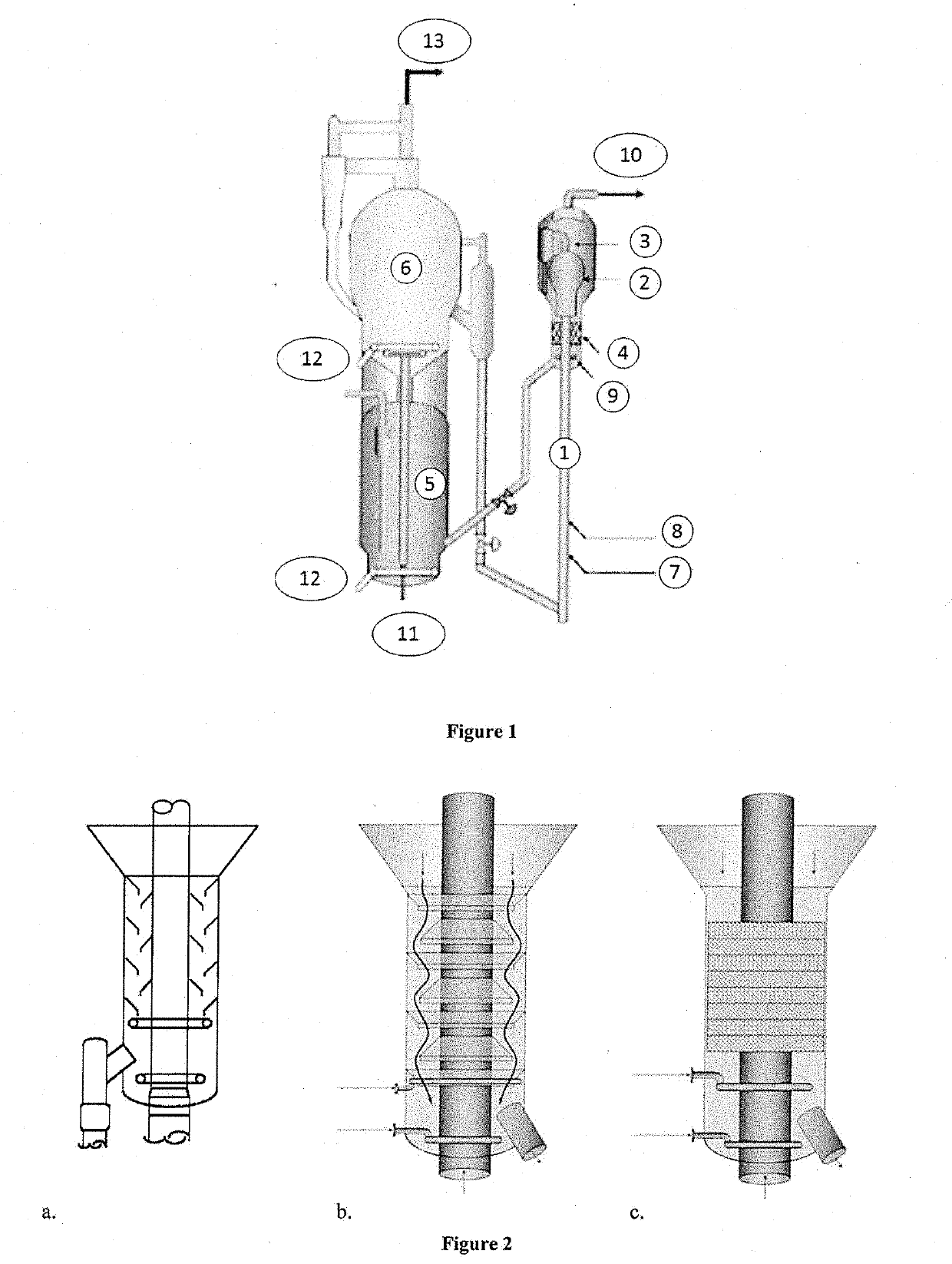
[0046]The present invention may be defined as a packing of three-dimensional structure intended notably to equip strippers of catalytic cracking units, and more generally of units which are to achieve as homogenous as possible contact between a gas phase and a dispersed solid phase, whatever the direction followed within said packing. This is what will be referred to in the remainder of the text as an anisotropic packing with three-dimensional structure.
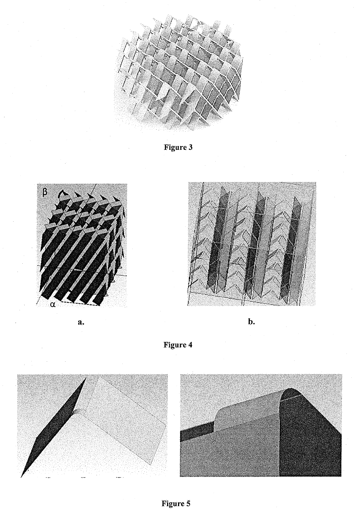
[0047]FIG. 4a depicts one type of packing according to the present invention.
[0048]The strips of document U.S. Pat. No. 6,224,833 are replaced here by rows of chevrons, which amounts to creating a fold that is symmetrical and along the longitudinal axis for each strip, the chevrons still being distributed in two planes forming between them an angle alpha comprised between 20° and 70°, preferably between 45° and 60°.
[0049]Each row of chevrons may be defined with respect to the two planes of the fold which between them form an angle be...
PUM
 Abstract
Description
Claims
Application Information
 - R&D Engineer
- R&D Manager
- IP Professional
- Industry Leading Data Capabilities
- Powerful AI technology
- Patent DNA Extraction
Browse by: Latest US Patents, China's latest patents, Technical Efficacy Thesaurus, Application Domain, Technology Topic, Popular Technical Reports.
© 2024 PatSnap. All rights reserved.Legal|Privacy policy|Modern Slavery Act Transparency Statement|Sitemap|About US| Contact US: help@patsnap.com