
Rotary polarized light emitting body, rotary polarized light emitting device, and manufacturing method therefor

a technology of light emitting device and light emitting body, which is applied in the direction of semiconductor devices, solid-state devices, organic semiconductor devices, etc., can solve the problems of product cost problems, deterioration of visibility and light emission efficiency, etc., and achieve the effect of minimizing the reflection of external ligh

Active Publication Date: 2020-04-09
IUCF HYU (IND UNIV COOP FOUND HANYANG UNIV)
View PDF0 Cites 0 Cited by
  • Summary
  • Abstract
  • Description
  • Claims
  • Application Information

AI Technical Summary

Benefits of technology

The present patent provides a way to make a rotating light emitting device that reduces the reflection of external light and maximizes the efficiency of providing light to the viewer. It also allows for a higher rotary polarization ratio. This technology affects how light is emitted from the device, and can improve visibility and reduce glare.

Problems solved by technology

However, according to the conventional technology, a product cost problem may be caused due to an expensive phase difference film.
Further, by the polarized plate, a portion of the light emitted from the organic light emitting layer may be blocked by the polarized plate, deteriorating visibility and light emission efficiency.

Method used


Image

  • Rotary polarized light emitting body, rotary polarized light emitting device, and manufacturing method therefor
  • Rotary polarized light emitting body, rotary polarized light emitting device, and manufacturing method therefor
  • Rotary polarized light emitting body, rotary polarized light emitting device, and manufacturing method therefor

Examples


first embodiment

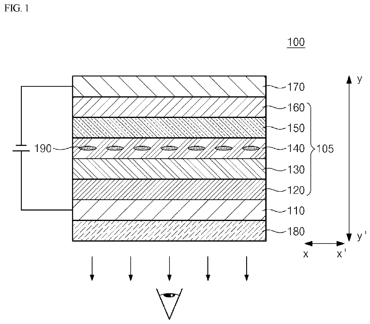
[0064]Referring to FIG. 1, the display 100 according to the present disclosure may include a first electrode 110, a second electrode 170, a light exiting layer 105, and a polarizing layer 180. Then, the elements may be laminated in the sequence of the polarizing layer 180, the first electrode 110, the light exiting layer 100, and the second electrode 170 in a direction from y′ to y, and the light exiting from the light exiting layer 105 may be provided for a viewer in the direction of y′ to implement a bottom emission type display. Hereinafter, the elements will be described in detail.

[0065]The first electrode 110 may be an anode electrode that provides holes to the light exiting layer 105. The first electrode 110 may include a transparent electrode such that light passes through the first electrode 110.

[0066]It is apparent that if the work function of the first electrode 110 is smaller than that work function of the second electrode 170, the first electrode 110 may correspond to th...

second embodiment

[0175]FIG. 9 illustrates a partially cross-sectional view illustrating a display according to the present disclosure.

[0176]Referring to FIG. 9, the display according to the second embodiment of the present disclosure may have a structure in which a substrate (not illustrated), an active layer (not illustrated), a first electrode 210, a light exiting layer 205, a second electrode 270, a polarizing layer 280 are laminated in the sequence thereof in the direction of y′ toy.

[0177]The first electrode 210 according to the second embodiment, unlike the first electrode 110 of the first embodiment, may include an electrode material of a high conductivity having an opaque property such that a reflective surface is provided. For example, the first electrode 210 may include a transparent conductive material layer having a high work function, such as indium-tin-oxide (ITO), and a reflective material layer such as silver (Ag) or a silver (Ag) alloy.

[0178]The first electrode 210 may be a sharing e...


PUM

PropertyMeasurementUnit
distortion angleaaaaaaaaaa
peak wavelengthsaaaaaaaaaa
peak wavelengthaaaaaaaaaa

Abstract

Provided is a display. A rotary polarized light emitting device includes: a first electrode; a second electrode; a light exiting layer, first light having a polarization state in which the first light rotates in a first direction, and exit, toward the second electrode, second light having a polarization state in which the second light rotates in a second direction that is opposite to the first direction.

Description

CROSS-REFERENCE TO RELATED APPLICATIONS[0001]This application is a continuation application of PCT application filed on May 23, 2018 and assigned Serial No. PCT / KR2018 / 005812, and which claims priority from Korean Patent Application No. 10-2017-0063675 filed with the Korean Intellectual Property Office on May 23, 2017, Korean Patent Application No. 10-2017-0076752 filed with the Korean Intellectual Property Office on Jun. 16, 2017, Korean Patent Application No. 10-10-2018-0056468 filed with the Korean Intellectual Property Office on May 17, 2018, The entire disclosures of above patent applications are incorporated herein by reference.BACKGROUND1. Field of the Invention[0002]The present invention relates to a light emitting body, a rotary polarized light emitting body and a rotary polarized light emitting device of a display, and a method for manufacturing the same, and more particularly, to a light emitting body and a display which minimizes reflection by external light and maximize...

Claims


Application Information

Patent Timeline
Patent Type & Authority Applications(United States)
IPC IPC(8): H01L51/52H01L51/56H10K99/00
CPCH01L51/0078H01L51/5092H01L51/5072H01L51/0072H01L51/56H01L51/5012H01L51/5293H01L51/5278H01L2251/5307H01L51/5088H01L27/3244H01L51/5056H01L2251/5315H01L51/5206H01L51/0043H01L51/5221H01L51/0073H01L51/0039H10K50/115H10K50/15H10K50/16H10K50/11H10K59/8793H10K59/8791H10K50/868H10K50/19H10K50/81H10K50/82H10K71/00H10K50/17H10K50/171H10K59/12H10K85/115H10K85/151H10K85/311H10K85/6572H10K85/6574H10K2102/3023H10K2102/3026
Inventor KIM, JAE-HOONLEE, YOU-JINYU, CHANG-JAE
Owner IUCF HYU (IND UNIV COOP FOUND HANYANG UNIV)
Learn More