
Natural view flat panel for cathode ray tube

a flat panel and cathode ray tube technology, applied in the field of cathode ray tube flat panel, can solve the problems of undesirable reflection of external light, distortion of screen image, and inability to compatibly use the flat panel in an existing cathode ray tube having a shadow mask, so as to reduce external light reflection, prevent the degradation of luminance, and reduce the effect of transmission ratio

Inactive Publication Date: 2005-07-05
SAMSUNG ELECTRONICS DEVICES CO LTD
View PDF14 Cites 0 Cited by
  • Summary
  • Abstract
  • Description
  • Claims
  • Application Information

AI Technical Summary

Benefits of technology

[0014]Accordingly, the present invention is directed to a flat panel that substantially eliminates one or more of the problems due to limitations and disadvantages of the related art.
[0015]A feature of an embodiment of the present invention is to provide a flat panel for a cathode ray tube in which a screen image may be realized on the flat panel without appearing concave.
[0016]Another feature of an embodiment of the present invention is to provide a flat panel for a cathode ray tube that displays a screen image that does not appear concave and which flat panel is capable of using existing masks to achieve such visual effect.
[0023]The panel has a high transmission ratio of 60% or more for preventing the degradation of luminance due to a difference in thickness between the central area and the peripheral area.
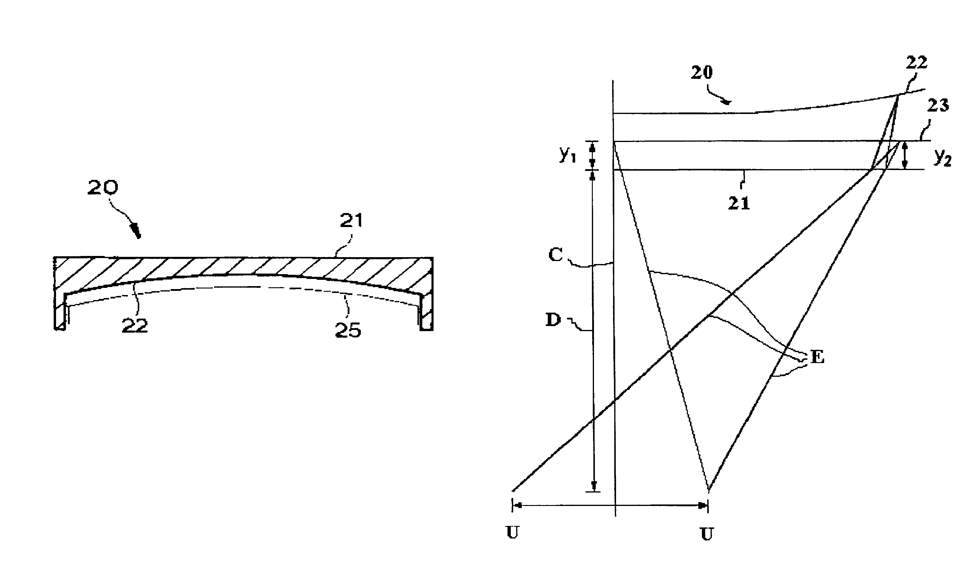
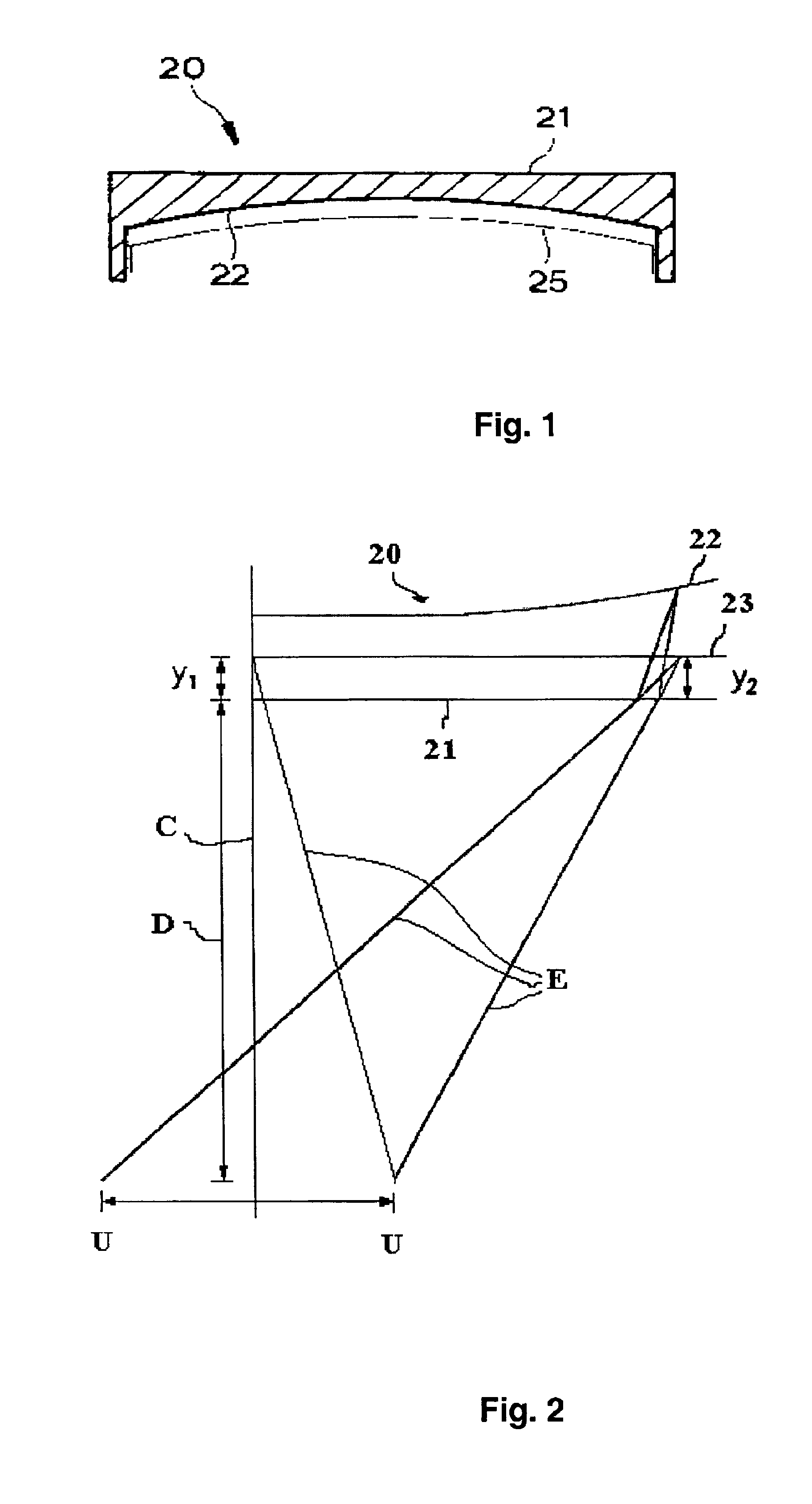
[0024]In the flat panel for a cathode ray tube of the present invention, the outer surface minimizes external light reflection and improves the display and appearance of screen images, and the inner surface allows the realization of natural images by preventing screen distortion due to the refraction of the screen image while passing through the flat panel.

Problems solved by technology

Such prior art panels, however, have limitations in terms of undesirable reflection of external light and distortion of the screen image as the outer surface is not flat.
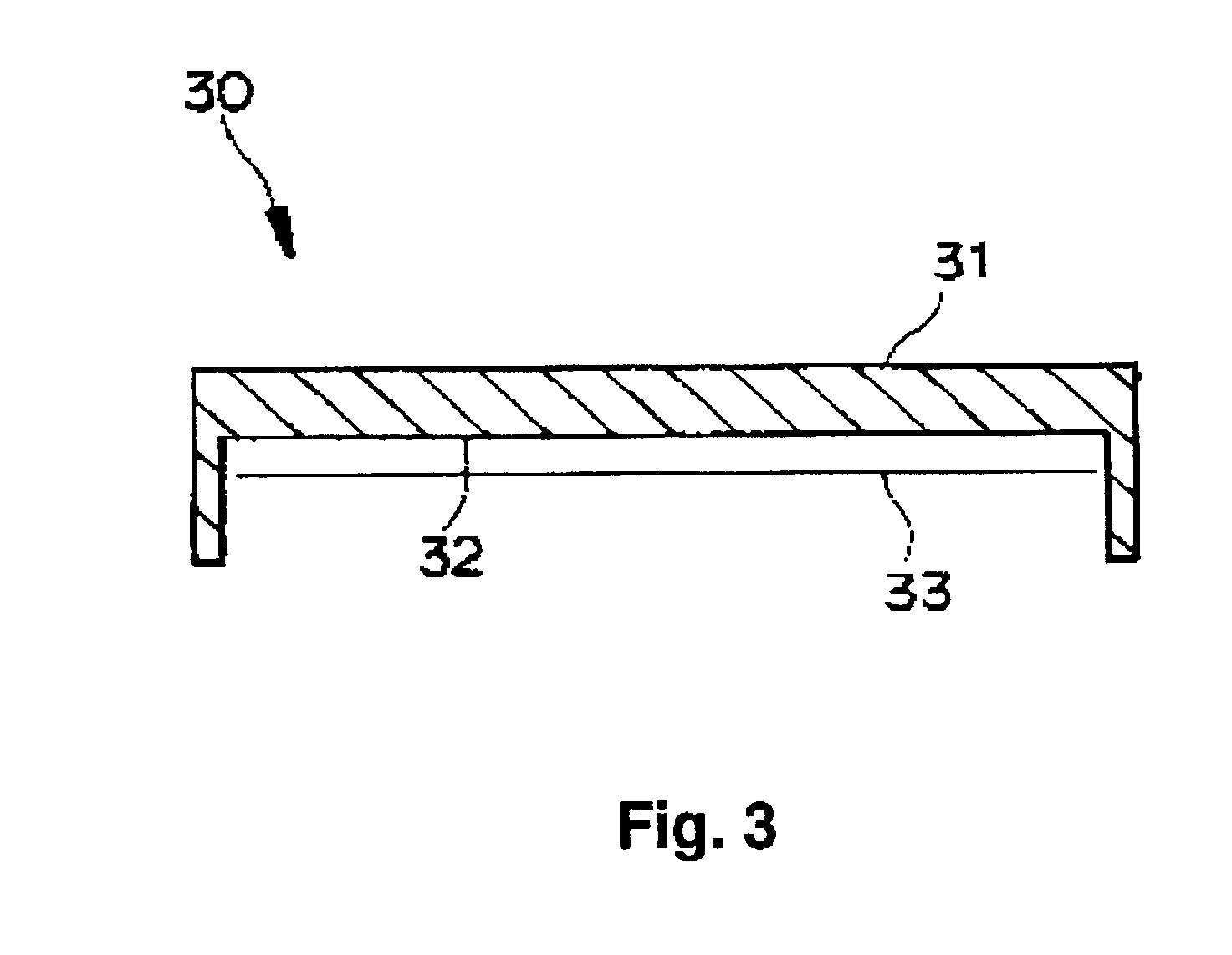
Such a conventional flat panel 30, however, has a disadvantage in that a natural screen image may not be realized due to a screen distortion phenomenon wherein the screen image appears to be concave inwardly as the size of the panel increases due to the refraction of the screen image along the sight or eye line as it passes through the flat panel 30.
Further, the color selection function becomes limited to the flat tension mask or the aperture grill forming a mask surface by the tension force, so that it is impossible to compatibly use the flat panel in an existing cathode ray tube having a shadow mask.

Method used


Image

  • Natural view flat panel for cathode ray tube
  • Natural view flat panel for cathode ray tube
  • Natural view flat panel for cathode ray tube

Examples


Embodiment Construction

[0030]Reference will now be made in detail to a preferred embodiment of the present invention, examples of which are illustrated in the accompanying drawings.

[0031]As shown in FIG. 1 and FIG. 2, a flat panel for a cathode ray tube is usually manufactured with a transparent glass plate. The flat panel 20 has an inner surface 22 which is provided with a phosphor surface formed by coating phosphor substances of three colors: red, green and blue, to be uniformly and regularly aligned in the shape of dots, and a non-phosphor substance such as graphite coated between the phosphor substances for preventing degradation of contrast and purity due to external incidental light.

[0032]Further, in order to improve the luminance of the phosphor surface, an aluminum thin film is evaporated on the phosphor substances.

[0033]The phosphor substances of the three colors: red, green, and blue, are irradiated with electron beams deflected by a deflection yoke, to emit light of corresponding colors, wherei...


PUM


Abstract

A flat panel for a cathode ray tube for preventing a screen image from being shown concavely to a user or viewer includes a flat outer surface and a non-spherically formed inner surface, the non-spherically formed inner surface satisfying formula 1:y1≦y2  (formula 1)wherein y1 represents a vertical distance between the outer surface and a refracted screen image on a central axis of the panel, and y2 represents a vertical distance between the outer surface and the refracted screen image in peripheral areas other than the central axis of the panel, and the panel has a high transmission ratio equal to or greater than about 60% for preventing degradation of luminance due to a difference in thickness between a central section and a peripheral section of the panel.

Description

[0002]This application is a continuation application of U.S. application Ser. No. 09 / 724,186 filed Nov. 27, 2000, now U.S. Pat. No. 6,459,196 B1, issued Oct. 1, 2002, which is a continuation of U.S. application Ser. No. 09 / 058,544 filed Apr. 10, 1998, now U.S. Pat. No. 6,160,344, issued Dec. 12, 2000.BACKGROUND OF THE INVENTION[0003]1. Field of the Invention[0004]The present invention relates to a panel for a cathode ray tube and, more particularly, to a flat panel for a cathode ray tube in which external light reflection is minimized, appearance is improved, natural view of screen images is possible, and to which a shadow mask may be applied.[0005]2. Description of the Related Art[0006]In general, a cathode ray tube includes a phosphor screen applied with three colors, red, green and blue, a shadow mask for selecting colors, an electron gun for emitting electron beams, and a deflection yoke for deflecting the electron beams on the phosphor screen, wherein the electron beams for the...

Claims


Application Information

Patent Timeline
Patent Type & Authority Patents(United States)
IPC IPC(8): H01J29/86
CPCH01J29/861H01J2229/862
Inventor CHO, YOON-HYOUNGSHIN, HYUN-JUNGPYUN, DO-HOUNLEE, KWANG-SIKAN, JAE-JINKIM, WON-HOKWON, YONG-GEOL
Owner SAMSUNG ELECTRONICS DEVICES CO LTD
Learn More