
Facemask with filter insert for protection against airborne pathogens

Active Publication Date: 2020-04-16
OCTO SAFETY DEVICES LLC
View PDF0 Cites 27 Cited by
  • Summary
  • Abstract
  • Description
  • Claims
  • Application Information

AI Technical Summary

Benefits of technology

This patent describes a respirator for air filters that can be easily replaced and / or biocidal. It has a vent that helps direct air exhaled by the wearer downward and backward towards their neck. The face mask has a flexible clip to compress the wearer's face and a pad with an opening to allow for ponytails and other hair styles. The technical effects of this patent are improved air filtration, comfortable and customizable fit, and improved breathability for a range of hair styles.

Problems solved by technology

These masks are often uncomfortable as they can stretch and / or pinch the skin around the ears and back of the head.
In addition, conventional masks are often required to be disposable as the strapping material tends to capture skin excretions as well as airborne particulates and pathogens and is difficult to clean.
Furthermore, conventional masks generally do not include a biocide-coated insert.
Those that do incorporate biocide-coated inserts often require rupturing an envelope to become operable.
This rupturing requirement introduces problems including wearers forgetting or being unable to rupture the envelope, or prematurely rupturing the envelope.
Another problem is conventional masks often provide a poor seal between the mask and the face due to the force of exhalations and the use of non-adjustable elastic fittings that do not provide enough force to keep the mask fitting snuggly.
These masks also provide limited protection for the medical professional by forming a physical barrier over the wearer's mouth and nose, preventing the accidental touching of these areas or the inhalation of airborne particles or droplets.
Rectangular cross-sectional elastics are often used, which can cause discomfort by stretching or pinching the skin around the ears and back of the head and by being one-size-fits-all and non-adjustable.
Yet, these designs suffer from the inherent flaws:(1) ties or elastic strap connections that connect along the sides of the mask near parallel to the upper nose seal area and thus, when sufficiently tied or tensioned to seal against the face, simultaneously pull the mask away from the upper nose seal area, preventing a complete seal;(2) wearers have the option of improperly fitting the mask to their face and / or insufficiently pinching inward the conformable strip in a generic nose bridge area;(3) little or no upward lift is provided by either ties or elastic straps for a proper seal in the chin area; and(4) exhalations inherently contain body heat, water (H2O) and Carbon Dioxide (CO2) and existing N95˜100 masks, ultimately capture and restrict breathability due to the accumulation of water then clogging the mask membrane to the degree that masks that include a front, one-way valve allow the emission of much of an amount of the above, the area above that vent inherently captures it all and restricts breathability and functionality while also creating discomfort for the wearer.
Creating such molds can be time-consuming and expensive.
The injection molding process also relies upon costly, high-pressure presses that can require highly trained personnel to oversee the manufacturing process.
Such constraints can drive up manufacturing costs.
Additionally, in at least some embodiments injection molds can have limited production capacity and inherent limitations that cannot facilitate rapid and / or simplified assembly processes as each piece of the facemask typically includes a subassembly that must be independently molded and assembled.
In some embodiments, such designs cannot be created via injection molding as the subassemblies would be too difficult to extract from the mold or would require complex, multi-pull molds that would still fail to create continuous elements.
Such shortcomings include a lack of adjustability and perpetuation of restricted and / or misdirected air-flow.

Method used


Image

  • Facemask with filter insert for protection against airborne pathogens
  • Facemask with filter insert for protection against airborne pathogens
  • Facemask with filter insert for protection against airborne pathogens

Examples


Embodiment Construction

)

[0162]As used herein “elastic” is intended to mean the state or quality of being elastic, flexible, resilient and / or adaptable.

[0163]As used herein “oblique” is intended to mean the state of being neither perpendicular nor parallel to a given line or surface; slanting; sloping.

[0164]As used herein “additive manufacturing” is intended to mean a process of making a three-dimensional solid object of virtually any shape from a digital model.

[0165]As used herein “diaphragm” is intended to mean a thin disk that vibrates when receiving or producing sound waves, as in a telephone, microphone, speaker or the like.

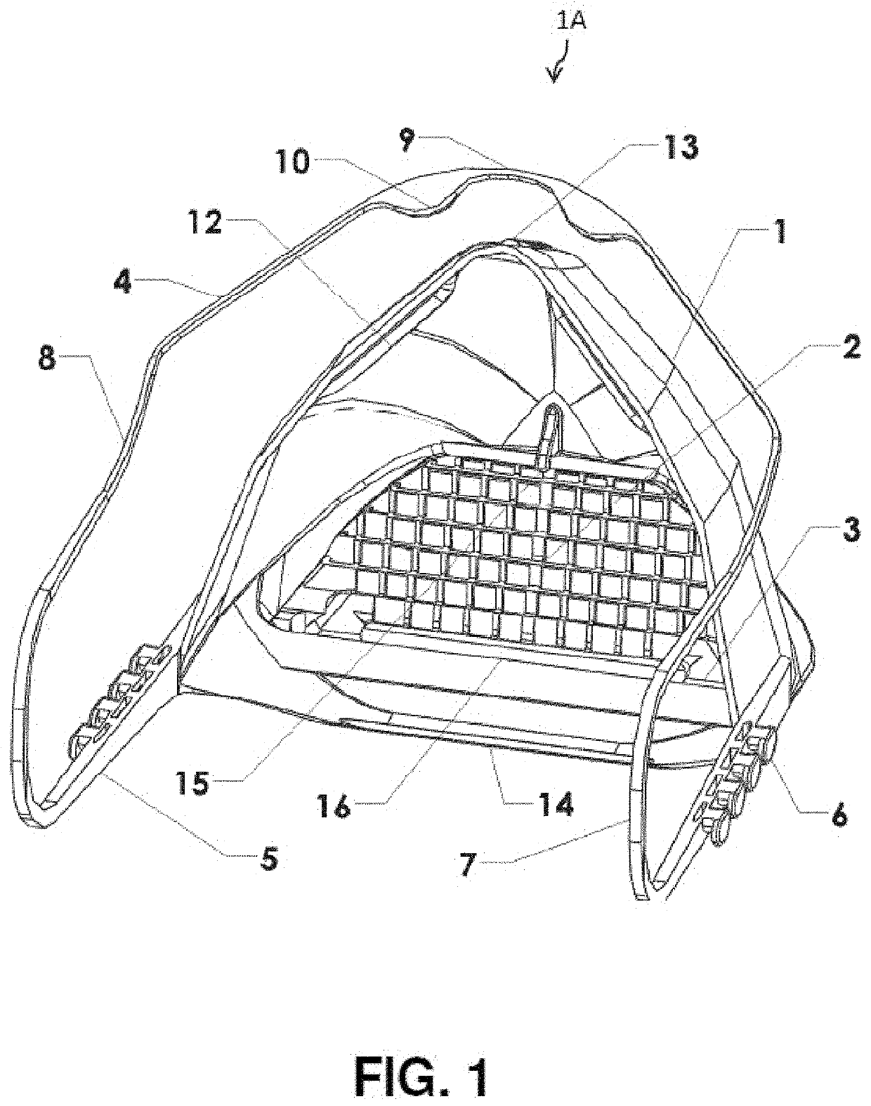
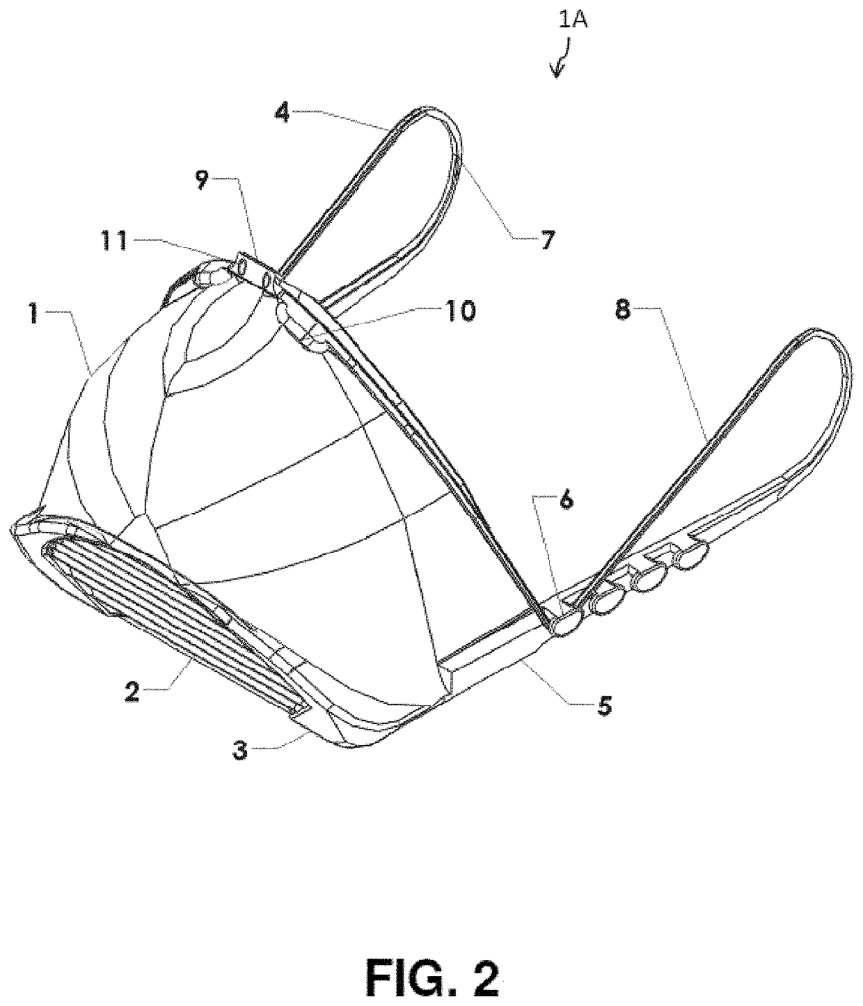
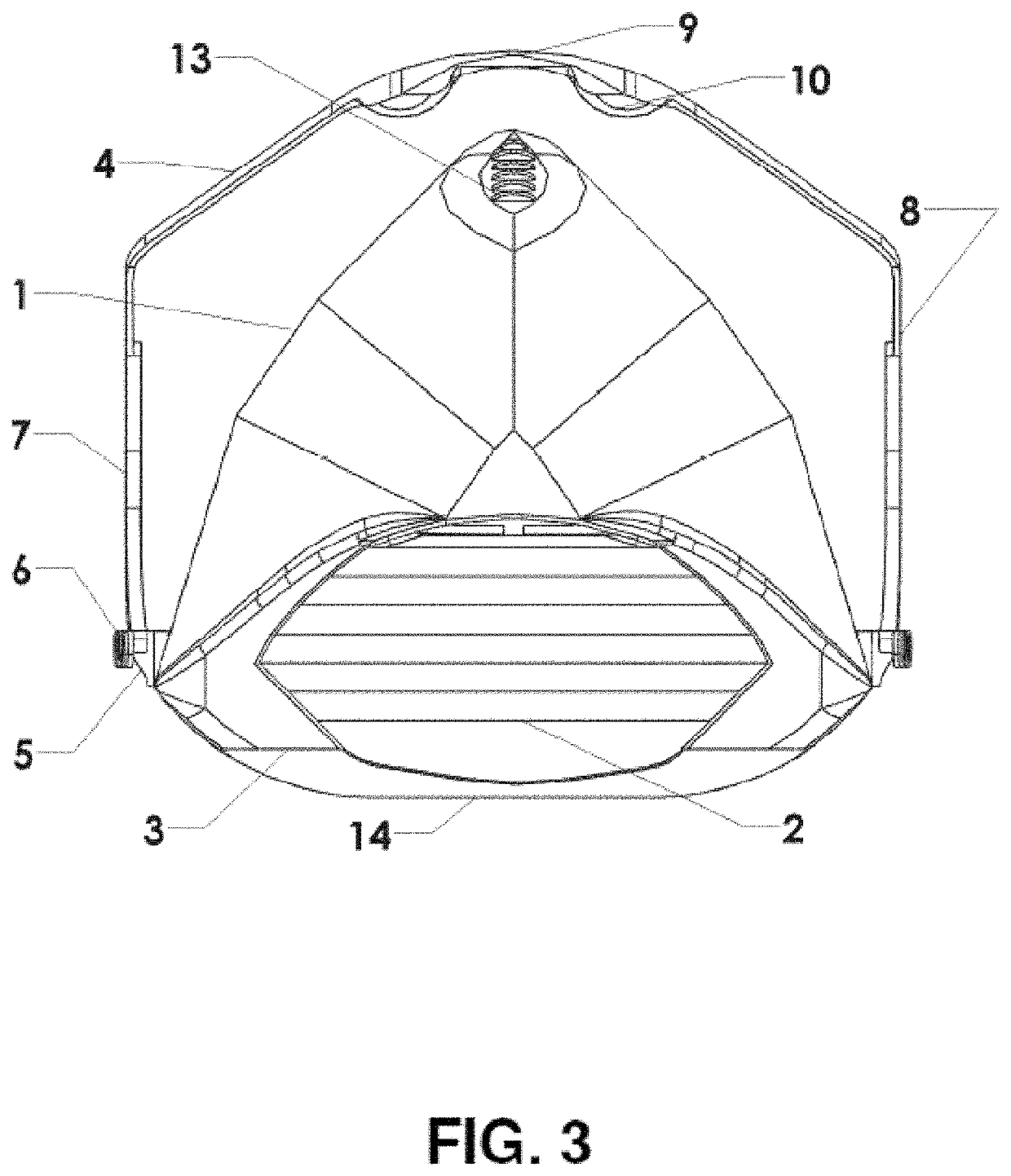
[0166]When describing elements of FIGS. 1-11, the same number is used to identify elements that are the same or substantially similar to each other in the different views illustrated in FIGS. 1-11.

[0167]Turning first to FIGS. 1 and 2, illustrating facemask assembly 1A, elastic facemask 1 has a plurality of air channels 2 and side vents 3 formed therein for directing exhaled air flo...


PUM


Abstract

A facemask assembly can include an interior air filter that is replaceable and / or contains biocidal elements. The filter can capture exhaled H2O to activate silver ions creating a biocidal environment. In some embodiments, at least part of the facemask is made via additive manufacturing. A facemask frame assembly can create a pleated filter to increase surface area and bring the filter material closer to the mouth and nose. The facemask can include a facial skirt customized to the facial geometry of the wearer. The facemask can have a permanently sealed filter than can withstand boiling and autoclaving temperatures so the mask system can be sterilized without disassembly. In some embodiments, the facemask has a visible display of how many times the facemask has been sterilized. In some embodiments, the mask includes a RFID device that can transmit how many times the facemask has been sterilized.

Description

CROSS-REFERENCE TO RELATED APPLICATION(S)[0001]This application claims priority to and is a continuation-in-part of U.S. patent application Ser. No. 15 / 226,877 entitled “Facemask with Filter Insert for Protection Against Airborne Pathogens” filed on Aug. 2, 2016. The '877 application claims priority to and is a continuation of U.S. patent application Ser. No. 14 / 801,808 entitled “Facemask with Filter Insert for Protection Against Airborne Pathogens” filed on Jul. 16, 2015. The '808 application is a Continuation-in-Part of U.S. patent application Ser. No. 14 / 477,840 also entitled “Facemask with Filter Insert for Protection Against Airborne Pathogens” filed on Sep. 4, 2014. The '840 application claimed priority benefits, in turn, from U.S. Provisional Patent Application Ser. No. 61 / 873,400 filed on Sep. 4, 2013, also entitled “Facemask with Filter Insert for Protection Against Airborne Pathogens”. This application also claims priority to and is a Continuation of International Patent A...

Claims


Application Information

Patent Timeline
Patent Type & Authority Applications(United States)
IPC IPC(8): A62B18/02A62B18/08A62B23/02
CPCA41D13/1161A62B23/025A62B18/082A41D13/1192A62B18/08A62B23/02A62B18/025A62B18/084B33Y80/00B33Y50/00B29C64/386
Inventor WATERFORD, STEVELYNN, ROBERT HUDSON
Owner OCTO SAFETY DEVICES LLC
Learn More