Belt offset correction device, fixing device, and image forming apparatus

a technology of fixing device and belt, which is applied in the direction of electrographic process apparatus, instruments, optics, etc., can solve the problems of complicated configuration of the belt offset adjustment member and the upsizing of the device, and achieve the effect of high accuracy

Active Publication Date: 2020-04-16
SHARP KK
View PDF2 Cites 0 Cited by
  • Summary
  • Abstract
  • Description
  • Claims
  • Application Information

AI Technical Summary

Benefits of technology

[0015]With this configuration, the force acting on a fixing nip N formed by the deformation of the elastic layer 171c of the fixing roller 171 is stabilized. As a result, the traveling performance of the fixing belt 173 is stabilized, whereby the offset control can be performed with high accuracy.

Problems solved by technology

However, the configurations of the members that correct the belts' offsets are complicated because at least one of the plurality of rollers stretching the endless belts is tilted in the configuration described in Japanese Patent Application Laid-Open No. 2012-198293, which could cause upsizing of the device.

Method used


Image

  • Belt offset correction device, fixing device, and image forming apparatus
  • Belt offset correction device, fixing device, and image forming apparatus
  • Belt offset correction device, fixing device, and image forming apparatus

Examples


first embodiment

[0045]Next, an example will be described, in which the belt offset correction device 300 according to the present embodiment is applied to a fixing device 17 of a belt fixing type.

Basic Configuration of Fixing Device

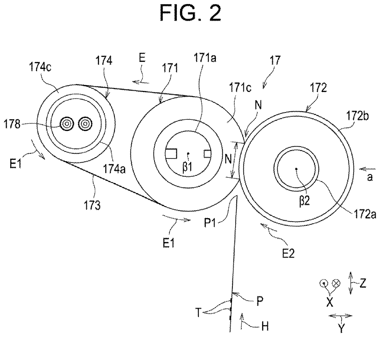
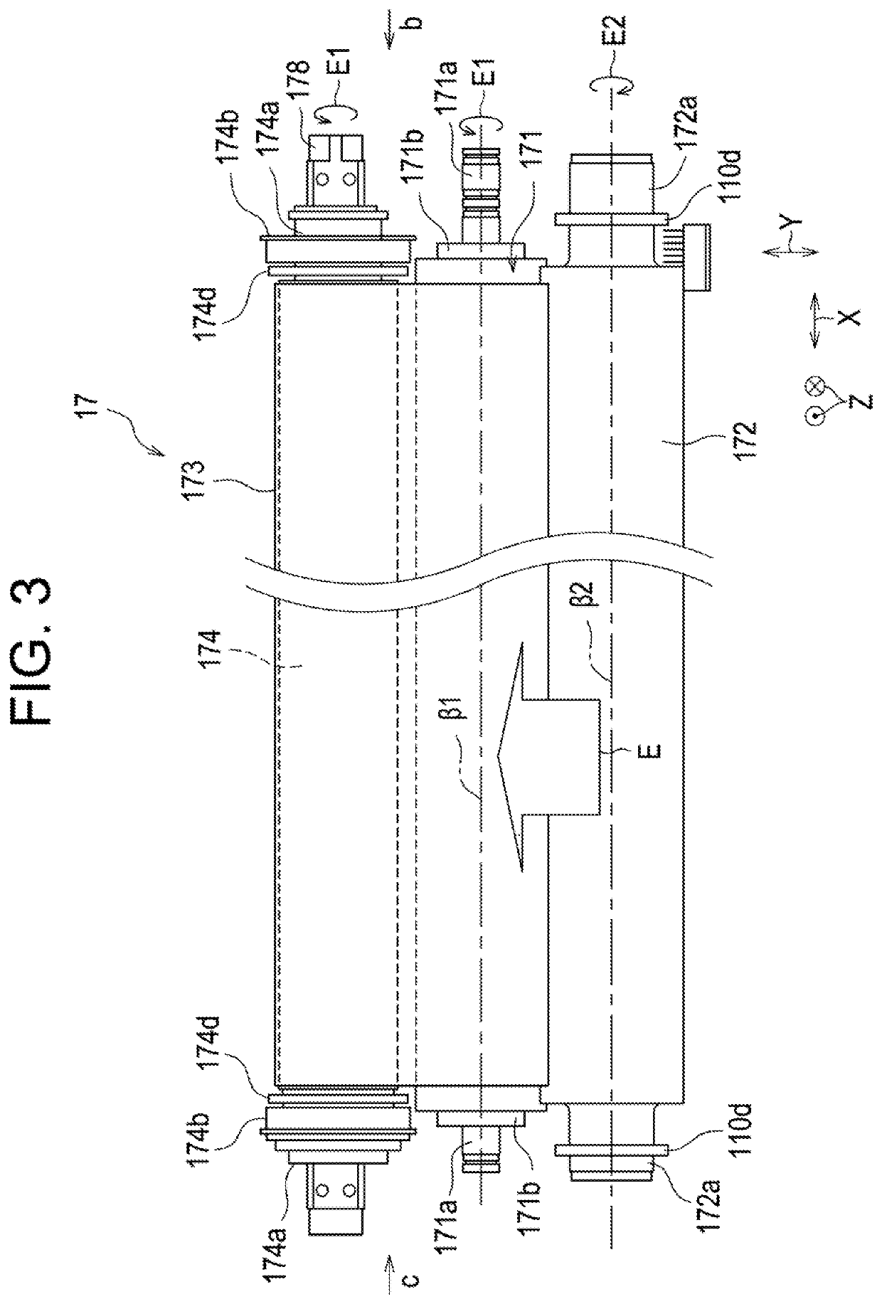
[0046]FIGS. 2 and 3 are a front view and a plan view showing a schematic configuration of the fixing device 17. FIG. 4A is a view of the fixing device 17 as viewed from the arrow b in FIG. 3, that is, as viewed from the rear side in the depth direction. FIG. 4B is a view of the fixing device 17 as viewed from the arrow c in FIG. 3, that is, as viewed from the front side in the depth direction. FIG. 5 is a view of the fixing device 17 as viewed from the arrow a in FIG. 2, that is, as viewed from the right side in the width direction of the apparatus. The fixing device 17 includes a plurality of belt rollers (the fixing roller 171 and the heating roller 174 in the present embodiment), an endless belt (the fixing belt 173 in the present embodiment) wound around the pluralit...

second embodiment

[0078]A fixing device 18 according to the second embodiment is the same as the fixing device according to the first embodiment except that a sheet heating element such as a ceramic heater is used as a heat source, and thus a duplicate description is omitted.

[0079]FIG. 10 is a front view of the fixing device 18. A fixing belt 230 is sandwiched not between a fixing roller and a pressure roller 231, but sandwiched between a sheet heating element 30 and a pressure roller 231, whereby a nip N is formed. The sheet heating element 30 is held by a guide member 32 and is reinforced by a reinforcing member 34 so that the guide member 32 does not warp even when pressed by the pressure roller 231.

[0080]The pressure roller 231 includes an elastic layer 231a in order to obtain an appropriate fixing nip N.

[0081]The moving mechanism of the pressure roller 231 is the same as the moving mechanism according to the first embodiment.

Effects of Second Embodiment

[0082]Even when the member (opposing member...

third embodiment

[0083]A fixing device 19 according to the third embodiment is different only in including second cams 132 that are disposed at positions opposed to the movement restrictors 110j, 110j of the pressure levers 110a and 110b on a rotation shaft 120 of a first cam 131 engaged with the guide 110h provided to the pressure lever 110b, and brought into contact with the movement restrictors 110j, 110j to restrict the deformation amount of the elastic layer 171c of the fixing roller 171, and in that the second cams 132 have such a shape as to change the distance between the axes of the fixing roller 171 and the pressure roller 172, and thus a duplicate description is omitted.

[0084]FIG. 11 is a perspective view of the fixing device 19 seen from an oblique direction, and also is a view a part of which is omitted for easy understanding of the structure. FIG. 12 is a view illustrating installation positions of the first cam 131 and the second cam 132. FIG. 13 is views illustrating the shape of the...


PUM


Abstract

A pair of pressure members are disposed at both ends of a pressure roller and rotatably support the pressure roller to press the pressure roller against a fixing roller including an elastic layer via a fixing belt. One of the pressure members that includes a fulcrum engaging section engaged with a rotation fulcrum at one end and is locked to a biasing member at a side opposite to the fulcrum engaging section is moved by a moving member in a direction intersecting a pressing direction of the pressure roller in a state where deformation of the elastic layer is regulated. Thus, a force acting on a fixing nip formed by the deformation of the elastic layer of the fixing roller is stabilized. As a result, the traveling performance of the fixing belt is stabilized, whereby the offset control can be performed with high accuracy.

Description

BACKGROUND OF THE INVENTIONField of the Invention[0001]The present invention relates to a belt offset correction device, a fixing device provided with the belt offset correction device, and image forming apparatuses such as a copying machine, a multi-function peripheral equipment, a printer, and facsimile equipment.Description of the Background Art[0002]Endless belts wound around a plurality of belt rollers are often offset in the width direction perpendicular to the circumferential direction of the belts due to the variations in components, or the like. For this reason, conventionally there have been proposed correcting devices that correct the belts' offsets. For example, Japanese Patent Application Laid-Open No. 2012-198293 discloses a configuration that in order to correct offsets of endless belts that are stretched and rotationally driven by a plurality of rollers, at least one of the plurality of rollers stretching the endless belts is tilted (see paragraph [0034], and FIG. 4 ...

Claims


Application Information

Patent Timeline
Patent Type & Authority Applications(United States)
IPC IPC(8): G03G15/20
CPCG03G2215/00143G03G15/2092G03G2215/00413G03G2215/2009G03G15/755G03G15/161G03G15/1615G03G2215/00168G03G2215/2016G03G15/2017G03G15/6529G03G15/2032
Inventor TSUKAMOTO, KIMIHIDE
Owner SHARP KK
Why Eureka
Try Eureka