
Switch

Active Publication Date: 2020-04-16
AUTONICS
View PDF0 Cites 0 Cited by
  • Summary
  • Abstract
  • Description
  • Claims
  • Application Information

AI Technical Summary

Benefits of technology

The patent improves the sensitivity and reliability of a switch while also making it smaller and less expensive to produce.

Problems solved by technology

However, the switch needs to maintain a distance between the magnets at a predetermined distance or more in order to prevent the cancellation of magnetic field lines between the magnets, and there is a problem that miniaturization of the switch is difficult to achieve.
Further, if the number of magnets is increased to improve sensitivity and / or reliability of the switch, there are problems that the size of the switch becomes large and the production cost increases.

Method used


Image

  • Switch
  • Switch
  • Switch

Examples


Embodiment Construction

[0025]Reference will now be made in detail to embodiments of the disclosure, examples of which are illustrated in the accompanying drawings. Wherever possible, the same reference numbers will be used throughout the drawings to refer to the same or like parts.

[0026]In general, a suffix such as “module” and “unit” may be used to refer to elements or components. Use of such a suffix herein is merely intended to facilitate description of the specification, and the suffix itself is not intended to give any special meaning or function.

[0027]It will be noted that a detailed description of known arts will be omitted if it is determined that the detailed description of the known arts can obscure the embodiments of the disclosure.

[0028]The accompanying drawings are used to help easily understand various technical features and it should be understood that the embodiments presented herein are not limited by the accompanying drawings. As such, the present disclosure should be construed to extend...


PUM


Abstract

A switch is disclosed. The switch includes a body; and an actuator configured to provide a magnetic force to the body and induce an electrical switching of the body, wherein the body includes a housing with a first surface; and a plurality of hall sensors sequentially disposed adjacent to the first surface, wherein the actuator includes a case with a second surface; and a first magnetic body and a second magnetic body sequentially disposed adjacent to the second surface, wherein the first magnetic body includes a first polarity; and a second polarity opposite to the first magnetic body, wherein the second magnetic body includes a third polarity; and a fourth polarity opposite to the third magnetic body, wherein the first polarity, the second polarity, the third polarity, and the fourth polarity are sequentially disposed along the second surface.

Description

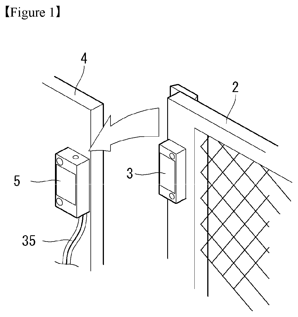
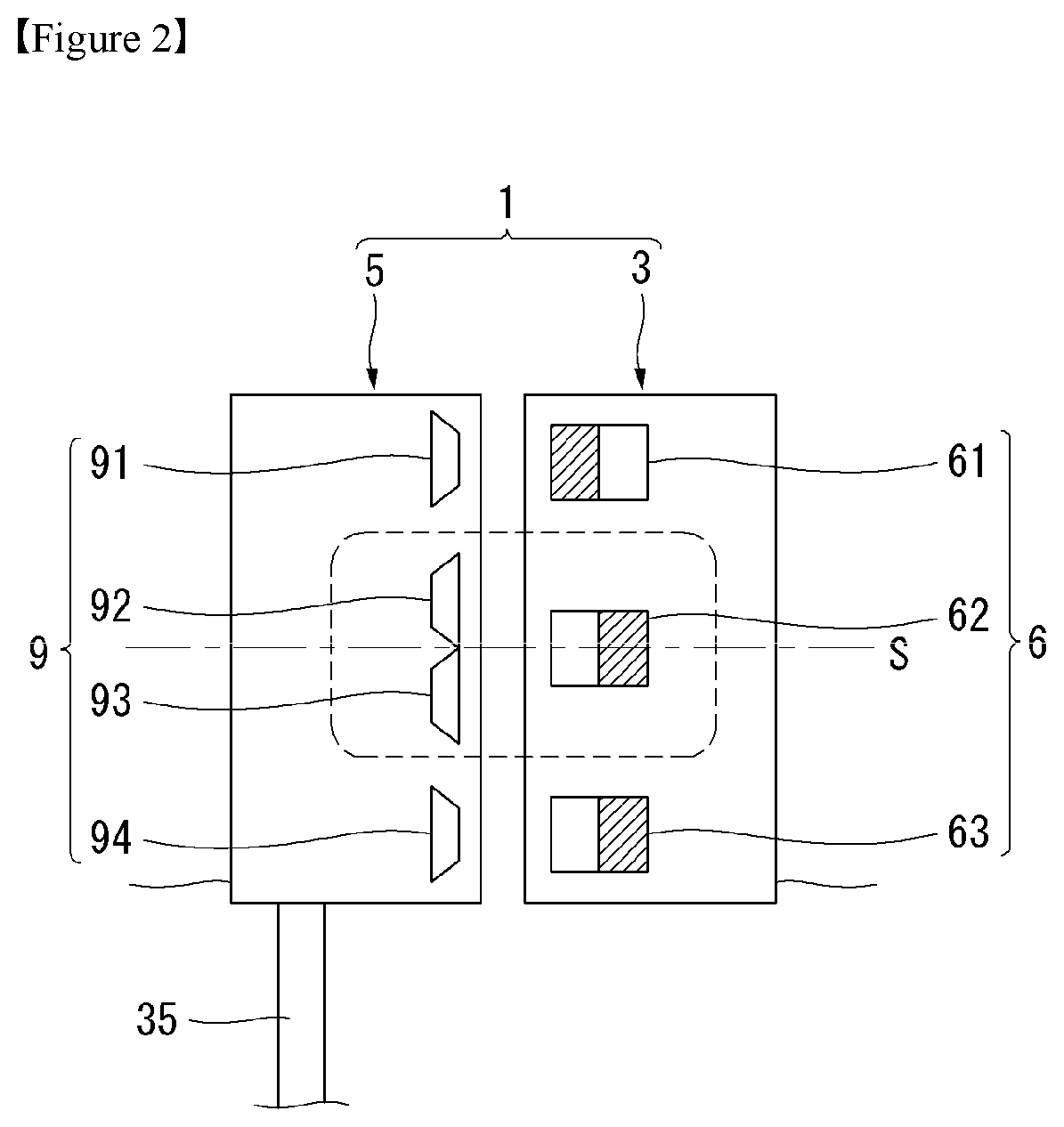
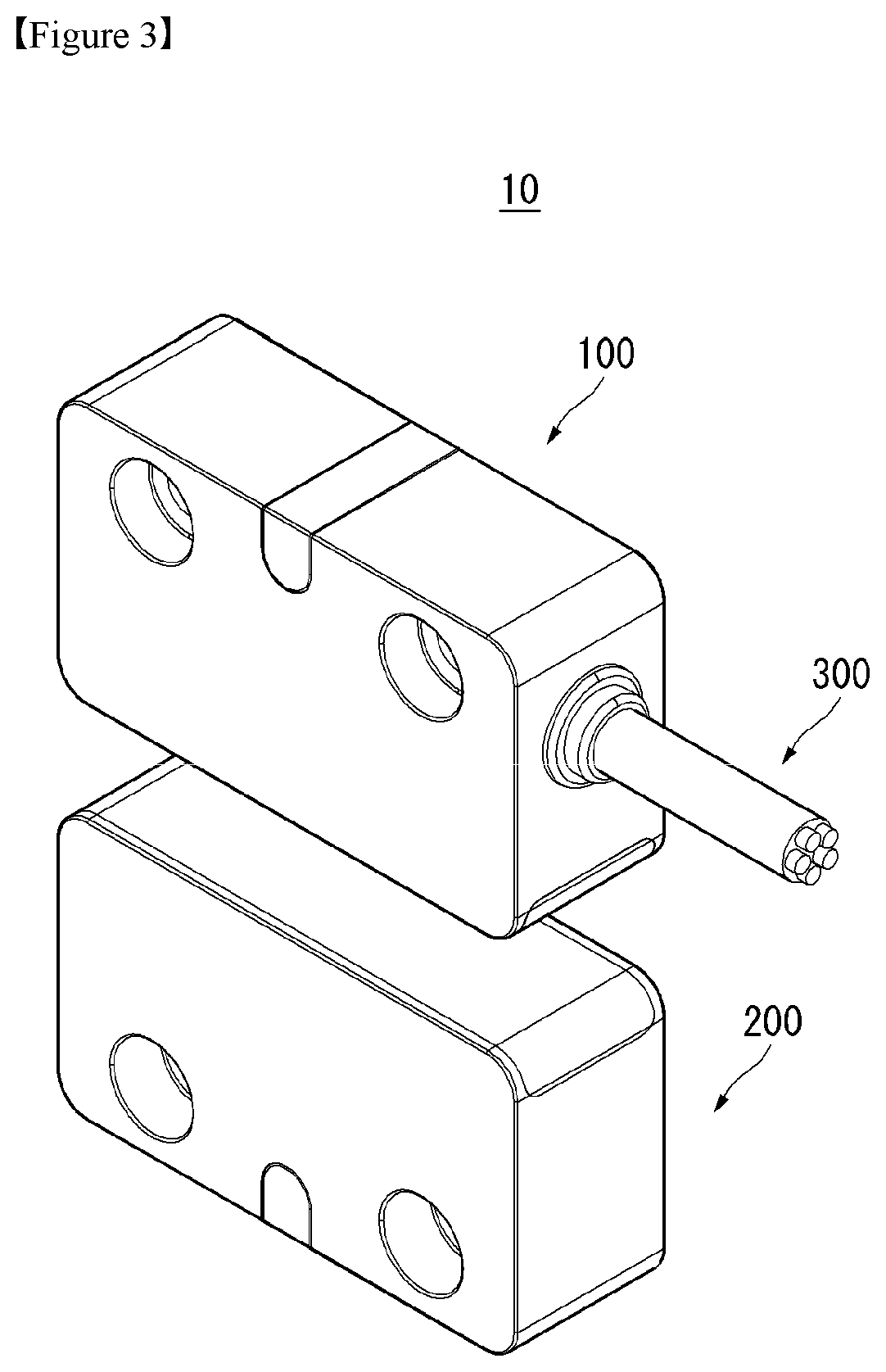
TECHNICAL FIELD[0001]The present disclosure relates to a switch. More particularly, the present disclosure relates to a non-contact switch.BACKGROUND ART[0002]A switch is a device controlling the flow of a current. A power source and an actuator can be separated for the stability of a system, and the switch electrically connects the power source to the actuator.[0003]As a kind of switch, there is a non-contact switch using a magnetic force. Because the non-contact switch does not have a mechanical contact, the non-contact switch does not have abrasion between contacts, has the good durability, and does not generate dust due to abrasion. Hence, the non-contact switch is suitable for an environment requiring dust proof.[0004]Referring to FIGS. 1 and 2, a switch 1 may be used to sense opening and closing of a door 2. A body 5 may be installed on a wall 4, and an actuator 3 may be installed on the door 2. The body 5 may include a plurality of hall sensors 9, and the actuator 3 may inclu...

Claims


Application Information

Patent Timeline
IPC IPC(8): H03K17/95G01D5/14
CPCH03K17/9517H03K17/9505G01D5/145
Inventor NOH, JONGEUNLIM, BYOUNGUK
Owner AUTONICS
Learn More