
Grill of top projecting and radiating type

a grill pan and projecting technology, applied in the field of small household appliances, can solve the problems of not being able to directly observe the size of fire, the inability to handle excess oil, and the objects being grilled will be leaked onto the heating body, etc., to achieve the effect of easy disassembly, easy speed up the cooking of food, and increased power output of the heating coil

Active Publication Date: 2020-04-23
YING WEI
View PDF1 Cites 1 Cited by
  • Summary
  • Abstract
  • Description
  • Claims
  • Application Information

AI Technical Summary

Benefits of technology

The present invention has several benefits. Firstly, it reduces the amount of smoke generated during grilling. The smoke can be removed using different methods, such as the top, bottom, and inner side of the support connection beam. Secondly, it improves the cooking speed as the heating coil can be increased power output without being obstructed by smoke. Lastly, the connecting screen outer cover and heating coil to theprojector housing can be easily disassembled for cleaning. The edges of the screen outer cover are provided with smooth steel wires for easy sliding. Additionally, the structure provides good heat dissipation and collection, and prevents the heating tube from being suspended on the reflector which could lead to its burnout.

Problems solved by technology

Disadvantageously, this design cannot handle excess oil, and the size of fire cannot be directly observed.
If the size of fire can be observed, the objects being grilled will be leaked onto the heating body.
However, the grilling pans of both the top projecting type and the downwardly projecting type face a big problem that is an inevitable problem during the grilling process, i.e., grilling smokes.
There are the following methods for controlling the smokes in the prior art: controlling temperature, which however means that the cooking time is prolonged; and minimizing the retention of grilling oil, which would make the food taste dry.

Method used


Image

  • Grill of top projecting and radiating type
  • Grill of top projecting and radiating type
  • Grill of top projecting and radiating type

Examples


example 2

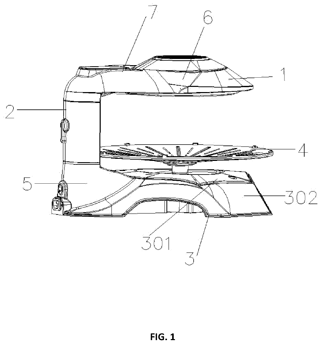
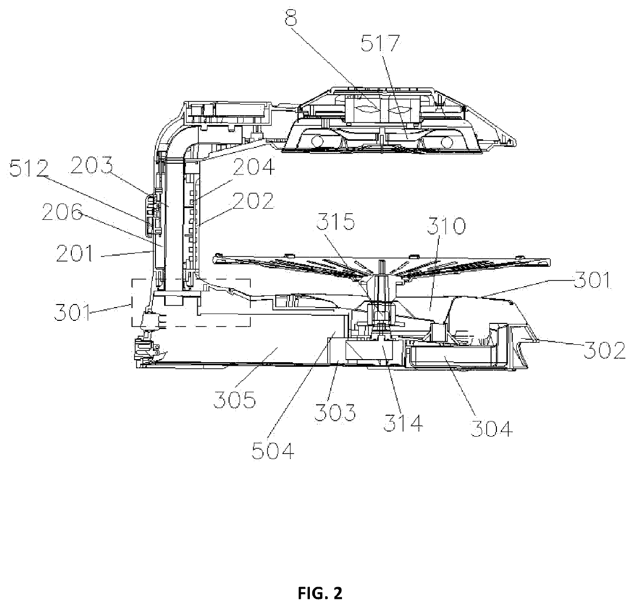
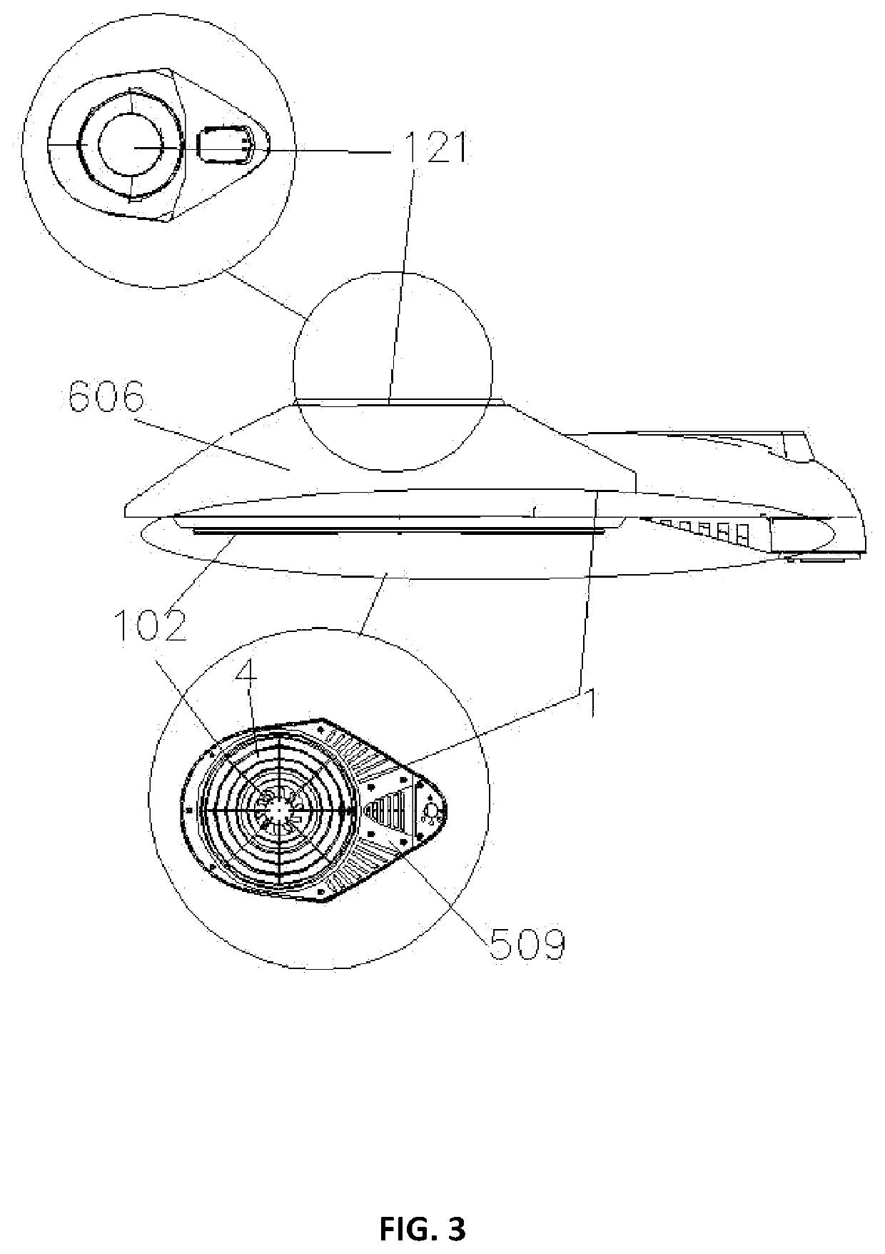
[0047]As shown in FIG. 2, a grill of top projecting and radiating type includes a projection heater 1, a support connection beam 2, a base 3, and a grilling pan 4. A support insertion seat 5 is provided on a side edge of the base. The support connection beam is arranged vertically upwards in the support insertion seat. The support connection beam supports and connects the projection heater. The projection heater is arranged transversely. The projection heater, the support connection beam, and the base form a sideway U-shaped structure. The grilling pan is arranged on the base directly below the projection heater. The projection heater and the grilling pan are arranged in parallel at an upper and lower locations, respectively. The infrared radiation from the infrared heating coil in the projection heater is maximally projected onto the grilling pan to grill food.

[0048]As shown in FIGS. 3 and 12, the projection heater includes a projection heating portion 6 and an insertion connection...


PUM


Abstract

A grill of top projecting and radiating type includes a projection heater, a support connection beam, a base and a grilling pan arranged on the base, wherein the base includes a substrate housing; an upper face of the substrate housing is provided with an oil collection upper housing; a grilling pan rotating motor is arranged in the substrate housing; the center of an upper surface of the grilling pan is low and the periphery thereof is high; a rotary socket pipe is fixedly arranged at the bottom center of the grilling pan; an electric motor shaft of the grilling pan rotating motor passes through the oil collection upper housing from bottom to top, is inserted into the rotary socket pipe and is then connected to the grilling pan to realize the synchronized rotation of the motor shaft and the grilling pan.

Description

TECHNICAL FIELD OF THE INVENTION[0001]The present invention relates to the technical field of small household appliances for daily use, and in particular to a grilling pan of top projecting and radiating type.BACKGROUND OF THE INVENTION[0002]Modern grilling pans are of bottom heating type. In this style, the grilling pan is directly heated from the bottom, and the grilling pan and the heating body do not directly contact the bottom and top, respectively. Disadvantageously, this design cannot handle excess oil, and the size of fire cannot be directly observed. If the size of fire can be observed, the objects being grilled will be leaked onto the heating body. Hence, grilling pans of the side heating type and top heating type appear. However, the grilling pans of both the top projecting type and the downwardly projecting type face a big problem that is an inevitable problem during the grilling process, i.e., grilling smokes. There are the following methods for controlling the smokes i...

Claims


Application Information

Patent Timeline
Patent Type & Authority Applications(United States)
IPC IPC(8): A47J37/06
CPCA47J37/0676A47J37/0745A47J37/046A47J37/0629
Inventor YING, WEI
Owner YING WEI
Learn More