
Electrically-driven rivet nut tool having multi-stage stroke and pull-riveting force adjustment

Active Publication Date: 2020-04-23
SHANGHAI ANZI IND +1
View PDF0 Cites 2 Cited by
  • Summary
  • Abstract
  • Description
  • Claims
  • Application Information

AI Technical Summary

Benefits of technology

The present invention provides an electrically-driven rivet nut tool with a multi-stage stroke and pull-riveting force adjustment. The tool has a pull screw, a primary gear, a motor, and a gear assembly for rotational movement. A control processor controls the motor, and a selection module selects the stroke length and provides an indication to the processor. A sensor assembly measures the amount of rotational movement of the primary gear, and the control processor controls the movement distance of the pull screw based on the selected stroke length. The tool has a count sensor that triggers the control processor to rotate the primary gear backward to the original position when the pull screw reaches the original position. The sensor assembly includes a plurality of sensor blocks on the gear surface, and the sensor signals are converted to electrical current. The technical effects of the invention include improved accuracy in rivet nut tooling and efficient and effective rivetting.

Problems solved by technology

The stroke, when exceeding the actual need too much, will affect the operating efficiency, waste the electrical energy, and shorten the service life of the riveting tool.
An excessive riveting force could damage rivet nuts, and the electrical energy could also be wasted.

Method used


Image

  • Electrically-driven rivet nut tool having multi-stage stroke and pull-riveting force adjustment
  • Electrically-driven rivet nut tool having multi-stage stroke and pull-riveting force adjustment

Examples


Embodiment Construction

[0054]The embodiments of the present invention are described below in detail with reference to the accompanying drawings.

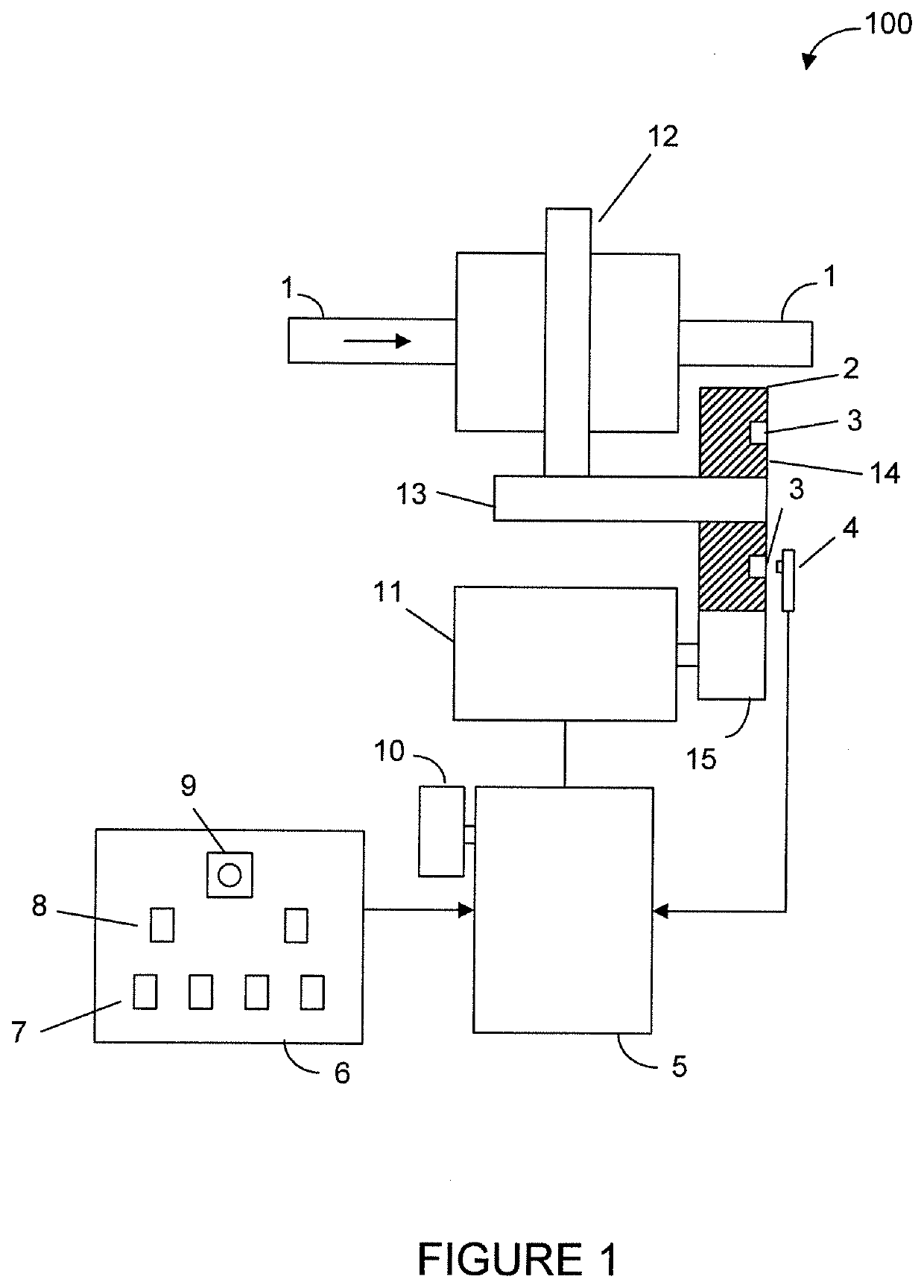
[0055]As shown in FIG. 1, the present invention provides an electrically-driven rivet nut tool 100 having a multi-stage stroke and pull-riveting force adjustment. The rivet nut tool has a selection button 9 for selecting a stroke value from multiple values of 2 mm, 4 mm, 6 mm and 8 mm, and a pull-riveting force value from 16000 N and 24000 N. A control processor 5 receives the input selected stroke value and pull-riveting force value. An extension plate is provided in a housing of the rivet nut tool, and a count sensor 4 is mounted on the extension plate. The count sensor 4 is positioned in relationship to sensing blocks 3 on a primary gear 2 and is connected to the control processor 5.

[0056]The stroke value in each selection corresponds to a preset count value in the control processor 5. According to an embodiment of the present invention, the preset count value ...


PUM

PropertyMeasurementUnit
Forceaaaaaaaaaa
Lengthaaaaaaaaaa
Lengthaaaaaaaaaa

Abstract

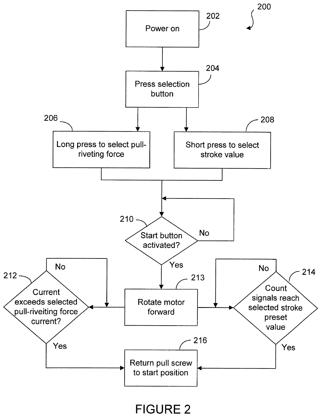
A rivet nut tool has a primary gear driven by a motor and a gear assembly coupled to the primary gear for rotation for moving a pull screw by a movement distance to achieve a stroke. The tool has a selection button for selecting a stroke value and a pull-riveting force. A control processor receives the selected stroke value and pull-riveting force. A count sensor is used to measure the rotational movement of a primary gear in terms of signal counts for determining the stroke achieved by the pull screw. The selected stroke value is presentable as a preset count value. When the signal count reaches the preset count value, or the motor current exceeds the current needed for the selected pull-riveting force, the control processor is configured to reverse the rotation direction of the motor so as to return the pull screw to its start position.

Description

CROSS REFERENCE TO RELATED PATENT APPLICATION[0001]This application claims benefit to Chinese Patent Application No. 201811216864.1, filed Oct. 18, 2018, which is hereby incorporated by reference in its entirety.TECHNICAL FIELD OF THE INVENTION[0002]The present invention relates to a riveting tool and, in particular, to an electrically-driven rivet nut tool having multi-stage stroke and pull-riveting force adjustment.BACKGROUND OF THE INVENTION[0003]For common electrically-driven rivet nut tools, the operating stroke is fixed. However, in the practical riveting operations, not all riveting strokes are required to be the same length. In some riveting operations, only half of the stroke or shorter is desired. In this case, generally, the excessive idle stroke beyond the operating stroke is achieved by mechanical adjustment. The stroke, when exceeding the actual need too much, will affect the operating efficiency, waste the electrical energy, and shorten the service life of the rivetin...

Claims


Application Information

Patent Timeline
IPC IPC(8): B21J15/28F16B37/06F16B37/08B21J15/50B21J15/26
CPCB21J15/28B21J15/26F16B37/062F16B37/08B21J15/50B25B21/00B25B23/147B21J15/10B25B27/0014
Inventor WU, MINGXIANG
Owner SHANGHAI ANZI IND
Learn More