Integrated starter generator drive having selective torque converter and constant speed transmission for aircraft having a constant frequency electrical system

a technology of starter generator and electrical system, which is applied in the direction of electric generator control, turbine/propulsion engine ignition, electric motor propulsion transmission, etc., can solve the problems of reducing reliability, reducing reliability, and requiring numerous air ducts, seals and air valves that are not only bulky but heavy, so as to reduce the load on the engine or the load.

Inactive Publication Date: 2005-01-04
HAMILTON SUNDSTRAND CORP
View PDF107 Cites 81 Cited by
  • Summary
  • Abstract
  • Description
  • Claims
  • Application Information

AI Technical Summary

Benefits of technology

Mechanical linkages may exist between the engine and the starter-generator to reduce the load on the engine or the load on the starter-generator. A torque converter may selectively couple and decouple the starter-generator to the engine. When the starter-generator is operated as a motor, the torque converter permits the starter-generator to rotate the turbine engine. When the starter-generator is operated as a generator, the tor

Problems solved by technology

These pneumatic systems require numerous air ducts, seals and air valves that are not only bulky but heavy.
Moreover, these systems add undesirable complexity to the aircraft, reducing reliability and increasing cost for aircraft operators.
However, the use of such a

Method used


Image

  • Integrated starter generator drive having selective torque converter and constant speed transmission for aircraft having a constant frequency electrical system
  • Integrated starter generator drive having selective torque converter and constant speed transmission for aircraft having a constant frequency electrical system
  • Integrated starter generator drive having selective torque converter and constant speed transmission for aircraft having a constant frequency electrical system

Examples


Embodiment Construction

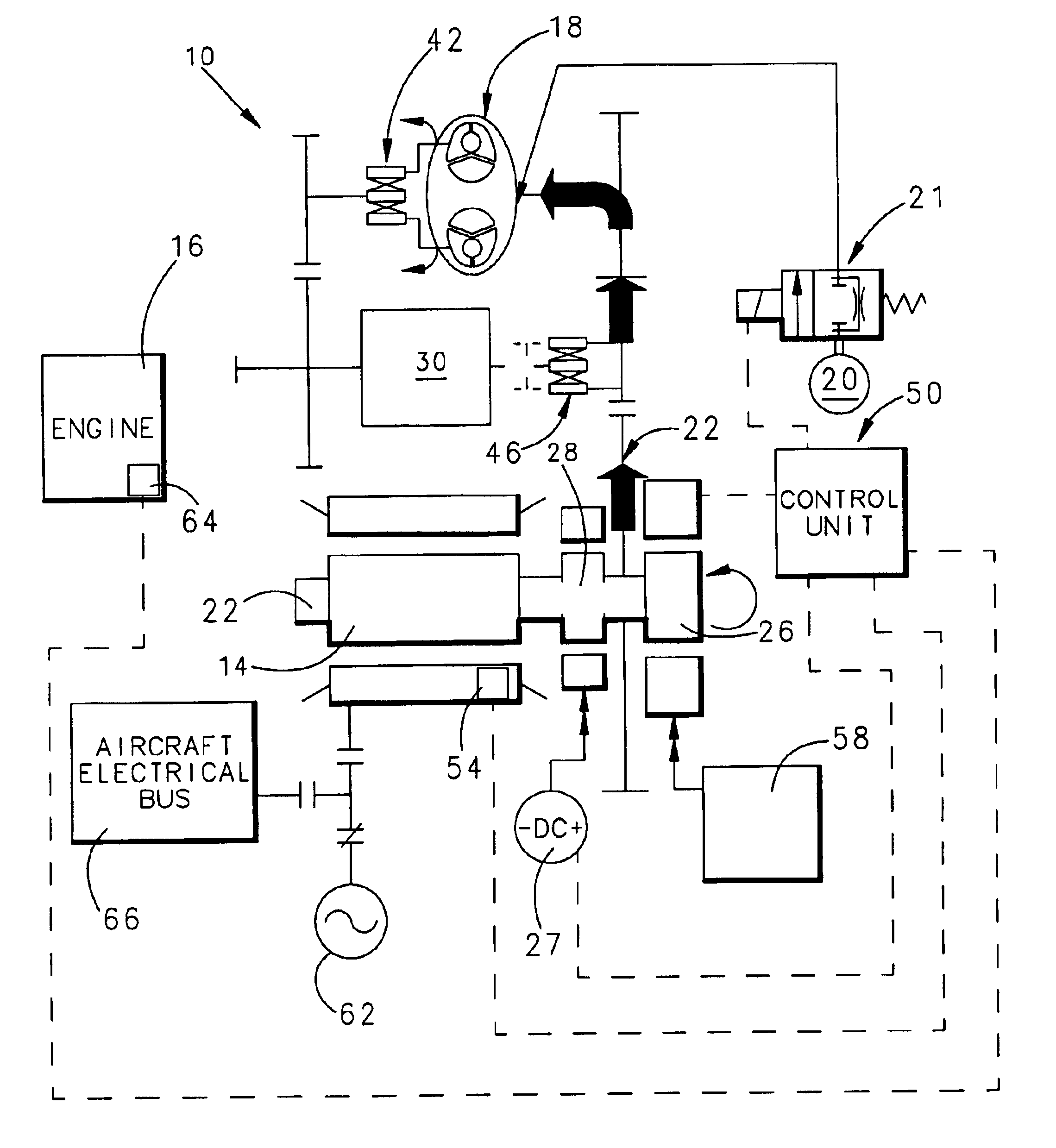
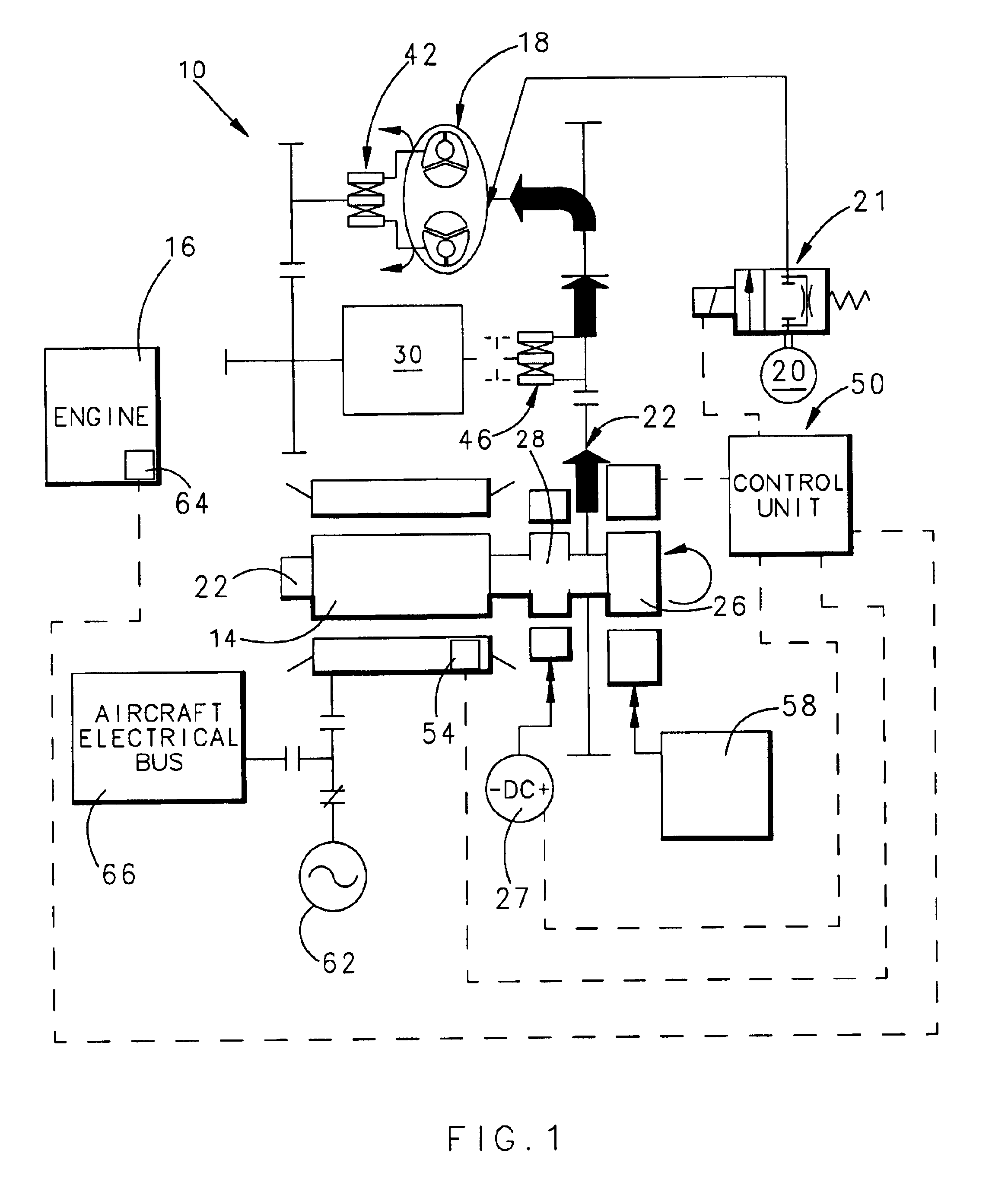
FIG. 1 illustrates a schematic representation of the inventive starter-generator 10. Like existing starter-generators, inventive starter-generator 10 employs dynamoelectric machine 14, which operates as both a motor and a generator. Dynamoelectric machine is a synchronous generator having rotor 22, which turns when the field windings of dynamoelectric machine 14 are charged by an alternating current from a power source. Support motor 26, such as a permanent magnet motor and generator, is mechanically linked to rotor 22 to accelerate it to a designated synchronous speed. Thus, as support motor 26 turns so too does rotor 22 of dynamoelectric machine 14.

Torque converter 18 may selectively couple and decouple the movement of rotor 22 to engine 16, such as a turbine engine for an aircraft. Torque converter 18 may be a hydraulic torque converter, which when filled with hydraulic fluid from hydraulic source 20 provides a coupling between rotor 22 and engine 16. As known, hydraulic source 2...


PUM


Abstract

A starter-generator for an aircraft engine comprises a dynamoelectric machine alternatively operable as a motor or as a generator, having a rotor. A support motor is coupled to the dynamoelectric machine to assist the machine. A torque converter selectively couples and decouples the rotor to the engine, coupling the rotor to the engine at some point when dynamoelectric machine is operated as a motor. A constant speed transmission has an input adapted to be connected to the engine and an output to be connected to the rotor. The unit provides a desired speed relation between input and output. The engine may be started by the dynamoelectric machine when operated as a motor through a first power train including the torque converter and may drive the dynamoelectric machine as a generator through a second power train including the constant speed transmission.

Description

BACKGROUND OF THE INVENTIONThis invention relates to a starter-generator for an aircraft engine, such as a turbine engine.A turbine engine employed in an aircraft may be started by supplying compressed air to an accessory air turbine motor having reduction gearing to drive the engine. Compressed air is provided by an auxiliary power unit or bleed air from another engine. These pneumatic systems require numerous air ducts, seals and air valves that are not only bulky but heavy. Moreover, these systems add undesirable complexity to the aircraft, reducing reliability and increasing cost for aircraft operators.Recently, aircraft manufacturers have commenced using electric starters for turbine engines. Such a starter adds little additional componentry and wiring to the aircraft because the starter takes advantage of the aircraft's existing electrical system. Thus, the starter does away with many of the components used to start the engine by compressed air.One approach to starting a turbi...

Claims


Application Information

Patent Timeline
IPC IPC(8): F02N11/04F02C7/26F02C7/268
CPCF02C7/268F02N11/04F02N11/006
Inventor KANDIL, MAGDY A.VANEK, LAURENCE D.ABBOT, JAMES L.
Owner HAMILTON SUNDSTRAND CORP
Why Eureka
Try Eureka