Vehicular air conditioning device

a technology of air conditioning device and battery, which is applied in vehicle heating/cooling devices, vehicle components, transportation and packaging, etc., can solve the problems of high temperature of battery during charging, and achieve accurate and efficient adjustment of battery temperature, efficient cooling of battery, and efficient consumption of power.

Active Publication Date: 2020-04-23
SANDEN CORP
View PDF0 Cites 11 Cited by
  • Summary
  • Abstract
  • Description
  • Claims
  • Application Information

AI Technical Summary

Benefits of technology

[0019]According to the present invention, in a vehicular air conditioning device to condition air of a vehicle interior, including a refrigerant circuit to let a refrigerant circulate in the order of a compressor, a heat exchanger for heat radiation, a pressure reducing unit, and a heat exchanger for heat absorption, and a control device, there are provided a battery temperature adjustment device to circulate a heat medium through a battery mounted in a vehicle, thereby cooling the battery, a refrigerant-heat medium heat exchanger to exchange heat between at least part of the refrigerant flowing out from the heat exchanger for heat radiation and the heat medium of the battery temperature adjustment device, and an expansion valve to decompress the refrigerant flowing into the refrigerant-heat medium heat exchanger. The control device controls the compressor or the expansion valve on the basis of a temperature Tw of the refrigerant of the refrigerant-heat medium heat exchanger to thereby adjust a temperature Tb of the battery to a predetermined target value TBO. It is therefore possible to eliminate the disadvantage that as in the case where the compressor is controlled with the temperature of the heat medium circulated in the battery temperature adjustment device, wasteful power is consumed in the compressor due to a lag in the control generated by the battery temperature adjustment device or the heat capacity of the heat medium. Consequently, it is possible to cool the battery efficiently by using the refrigerant circuit for conditioning air in the vehicle interior. In particular, since at least part of the refrigerant flowing out from the heat exchanger for heat radiation is decompressed by the expansion valve and made to flow into the refrigerant-heat medium heat exchanger, the temperature Tb of the battery can be accurately and efficiently adjusted to the target value TBO.
[0020]Here, as in the invention of claim 2, a temperature of the refrigerant in an inlet of the refrigerant-heat medium heat exchanger or a temperature converted from a pressure of the refrigerant in the inlet of the refrigerant-heat medium heat exchanger, or a temperature of the refrigerant in an outlet of the refrigerant-heat medium heat exchanger or a temperature converted from a pressure of the refrigerant in the outlet of the refrigerant-heat medium heat exchanger can be adopted as the temperature Tw of the refrigerant of the refrigerant-heat medium heat exchanger.
[0021]Further, as in the invention of claim 3, the control device sets the target value TBO of the temperature Tb of the battery as a target value TWO of the temperature Tw of the refrigerant of the refrigerant-heat medium heat exchanger, and controls the compressor or the expansion valve on the basis of the target value TWO and the temperature Tw of the refrigerant of the refrigerant-heat medium heat exchanger, whereby the temperature Tb of the battery can suitably be adjusted to the target value TBO. However, if the control device corrects the target value TWO of the temperature Tw of the refrigerant of the refrigerant-heat medium heat exchanger on the basis of the degree of lowering of the temperature Tb of the battery, it is possible to adjust the temperature Tb of the battery to the target value TBO more quickly.
[0022]In the above, as in the invention of claim 4, for example, there are provided an air flow passage through which air to be supplied to the vehicle interior flows, a radiator to let the refrigerant radiate heat, thereby heating the air to be supplied from the air flow passage to the vehicle interior, a heat absorber to let the refrigerant absorb heat, thereby cooling the air to be supplied from the air flow passage to the vehicle interior, and an outdoor heat exchanger disposed outside the vehicle interior to let the refrigerant radiate or absorb heat. The control device executes a heating mode to let the refrigerant discharged from the compressor radiate heat in the radiator, decompress the refrigerant from which the heat has been radiated, and then let the refrigerant absorb heat in the outdoor heat exchanger, thereby heating the vehicle interior, a dehumidifying mode to let the refrigerant discharged from the compressor radiate heat in the radiator and the outdoor heat exchanger, decompress the refrigerant from which the heat has been radiated, and then let the refrigerant absorb heat in the heat absorber, thereby dehumidifying the vehicle interior, and a cooling mode to let the refrigerant discharged from the compressor radiate heat in the outdoor heat exchanger, decompress the refrigerant from which the heat has been radiated, and then let the refrigerant absorb heat in the heat absorber, thereby cooling the vehicle interior. Further, in the cooling mode and / or the dehumidifying mode, the heat absorber constitutes the heat exchanger for heat absorption, the outdoor heat exchanger constitutes the heat exchanger for heat radiation, and at least part of the refrigerant flowing out from the outdoor heat exchanger is decompressed in the expansion valve and made to flow into the refrigerant-heat medium heat exchanger. Consequently, in an environment where the temperature of the battery is easily raised, the heat medium circulated in the battery temperature adjustment device is efficiently cooled by the refrigerant of the refrigerant circuit to enable the battery to be cooled.
[0023]In this case, as in the invention of claim 5, the control device may control an operation of the compressor on the basis of a temperature Te of the heat exchanger for heat absorption, and control a valve position of the expansion valve on the basis of the temperature Tw of the refrigerant of the refrigerant-heat medium heat exchanger. As in the invention of claim 7, the control device may control the operation of the compressor on the basis of the temperature Tw of the refrigerant of the refrigerant-heat medium heat exchanger, and control the valve position of the expansion valve on the basis of the temperature Te of the heat exchanger for heat absorption.
[0024]Then, in the case of the invention of claim 5, as in the invention of claim 6, the control device performs changing to control the operation of the compressor according to a target number of revolutions TGNCte of the compressor calculated based on the temperature Te of the heat exchanger for heat absorption, and when the target number of revolutions TGNCte is lowered to a predetermined low value, stop the supply of the refrigerant to the heat exchanger for heat absorption, and control the operation of the compressor according to a target number of revolutions TGNCtw of the compressor calculated based on the temperature Tw of the refrigerant of the refrigerant-heat medium heat exchanger. Thus, in the circumstance that there is no need for cooling of the vehicle interior by the heat exchanger for heat absorption, the control device performs changing to a state in which the refrigerant circuit is used only for the cooling of the battery, thereby making it possible to continue the cooling of the battery without hindrance.

Problems solved by technology

On the other hand, the battery becomes high in temperature during its charging, or due to self-heating during its discharging.
There is a risk that when the charging / discharging of the battery is performed under such circumstances, its deterioration progresses and soon the battery causes an operation failure to lead to breakage.

Method used


Image

  • Vehicular air conditioning device
  • Vehicular air conditioning device
  • Vehicular air conditioning device

Examples


Embodiment Construction

[0036]Hereinafter, description will be made as to embodiments of the present invention in detail with reference to the drawings.

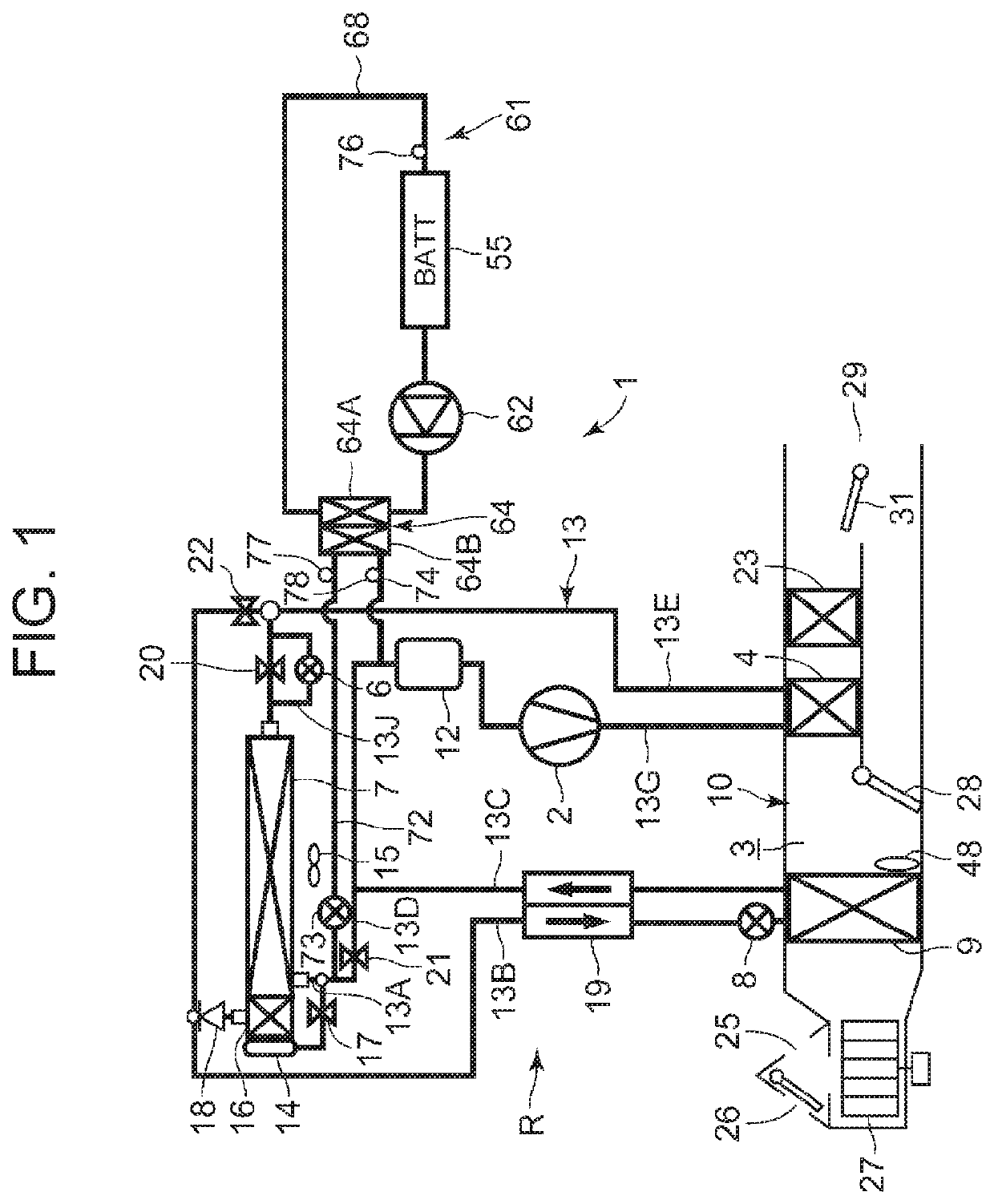
[0037]FIG. 1 illustrates a constitutional view of a vehicular air conditioning device 1 of an embodiment of the present invention. A vehicle of the embodiment to which the present invention is applied is an electric vehicle (EV) in which an engine (an internal combustion engine) is not mounted, and is provided with a battery 55 and runs with an electric motor for running (not shown in the drawing) which is driven by being supplied with power charged in the battery 55. The vehicular air conditioning device 1 of the present invention is also driven by the power of the battery 55.

[0038]That is, in the electric vehicle which is not capable of performing heating by engine waste heat, the vehicular air conditioning device 1 of the embodiment performs a heating mode by a heat pump operation in which a refrigerant circuit R is used. Further, the vehicular air condi...


PUM


Abstract

A vehicular air conditioning device is provided which is capable of cooling a heat medium of a battery temperature adjustment device by a refrigerant in a refrigerant circuit to improve operation efficiency when a battery is to be cooled. The vehicular air conditioning device includes a battery temperature adjustment device (61) for circulating a heat medium in a battery (55) to cool the same, a refrigerant-heat medium heat exchanger (64) for exchanging heat between at least part of the refrigerant flowing out from an outdoor heat exchanger (7) and the heat medium circulating in the battery temperature adjustment device, and an auxiliary expansion valve (73) for decompressing the refrigerant flowing into the refrigerant-heat medium heat exchanger. A control device controls a compressor (2) or the auxiliary expansion valve on the basis of a temperature Tw of the refrigerant of the refrigerant-heat medium heat exchanger to thereby adjust a battery temperature Tb to a target battery temperature TBO.

Description

CROSS-REFERENCE TO RELATED APPLICATIONS[0001]This application is a U.S. National Stage Patent Application under 37 U.S.C. § 371 of International Patent Application No. PCT / JP2018 / 010362, filed on Mar. 9, 2018, which claims the benefit of Japanese Patent Application No. JP 2017-081934, filed on Apr. 18, 2017, the disclosures of each of which are incorporated herein by reference in their entirety.TECHNICAL FIELD[0002]The present invention relates to an air conditioner of a heat pump system which conditions air of a vehicle interior of a vehicle, and more particularly, it relates to a vehicular air conditioning device which is suitable for a hybrid car and an electric vehicle each having a battery.BACKGROUND ART[0003]Due to actualization of environmental problems in recent years, hybrid cars and electric vehicles each of which drives a motor for running by power supplied from a battery have spread. Further, as an air conditioning device which is applicable to such a vehicle, there has ...

Claims


Application Information

Patent Timeline
Patent Type & Authority Applications(United States)
IPC IPC(8): B60H1/00B60H1/32B60H1/14
CPCB60H1/323B60H1/00278B60H1/143B60H2001/00307B60H1/00921B60H2001/00928B60H2001/00949
Inventor ISHIZEKI, TETSUYA
Owner SANDEN CORP
Why Eureka
Try Eureka