Charging station for charging electrical vehicles
a charging station and electrical vehicle technology, applied in the direction of parallel/serial switching, battery arrangement, safety/protection circuit, etc., can solve the problems of high power electronics, high cost, and high complexity of prior art charging stations, and achieve cost-effective manufacturing, simple and cost-efficient circuitry, and reduce the risk of charging station malfunction.
- Summary
- Abstract
- Description
- Claims
- Application Information
AI Technical Summary
Benefits of technology
Problems solved by technology
Method used
Image
Examples
first embodiment
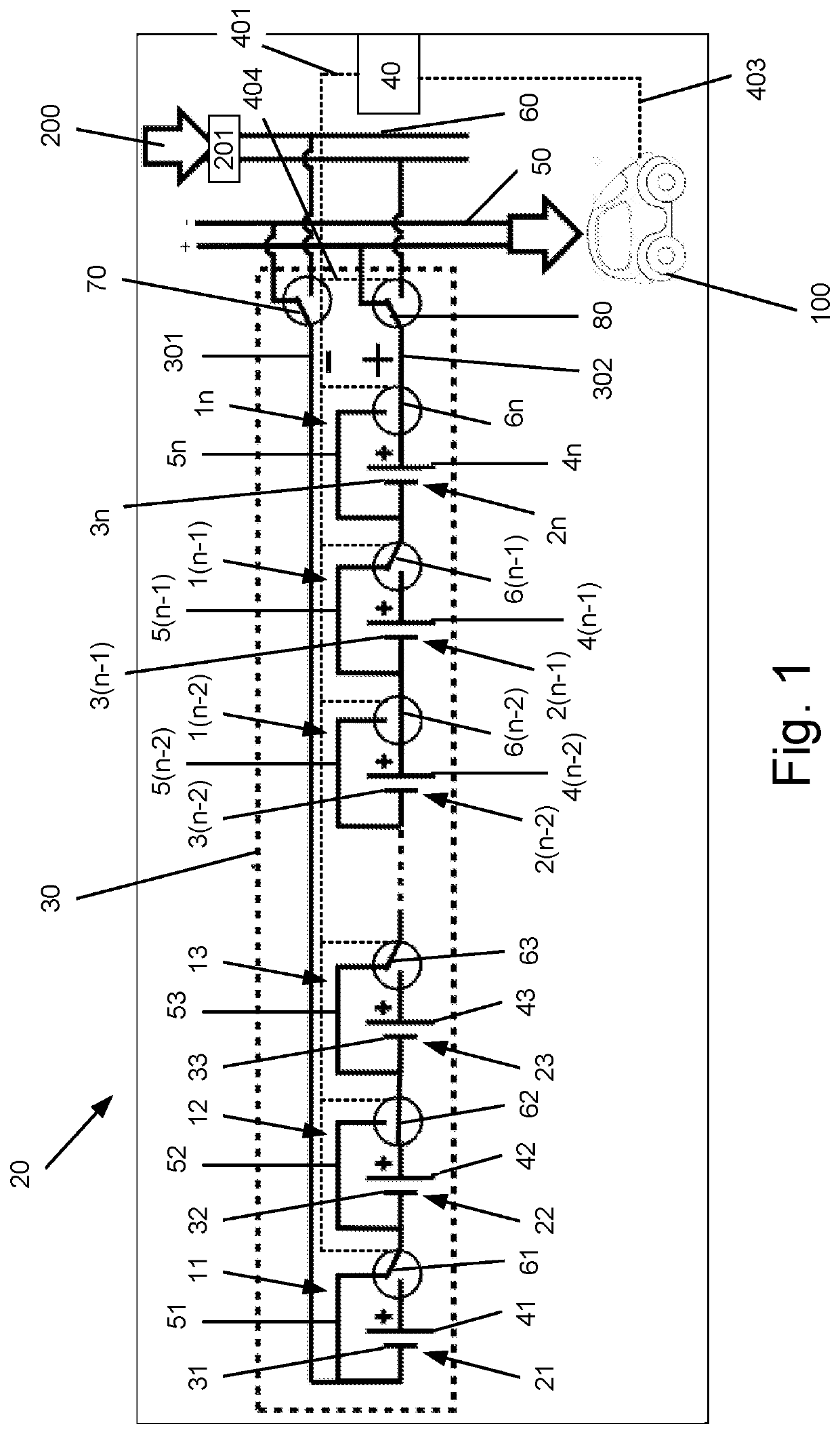
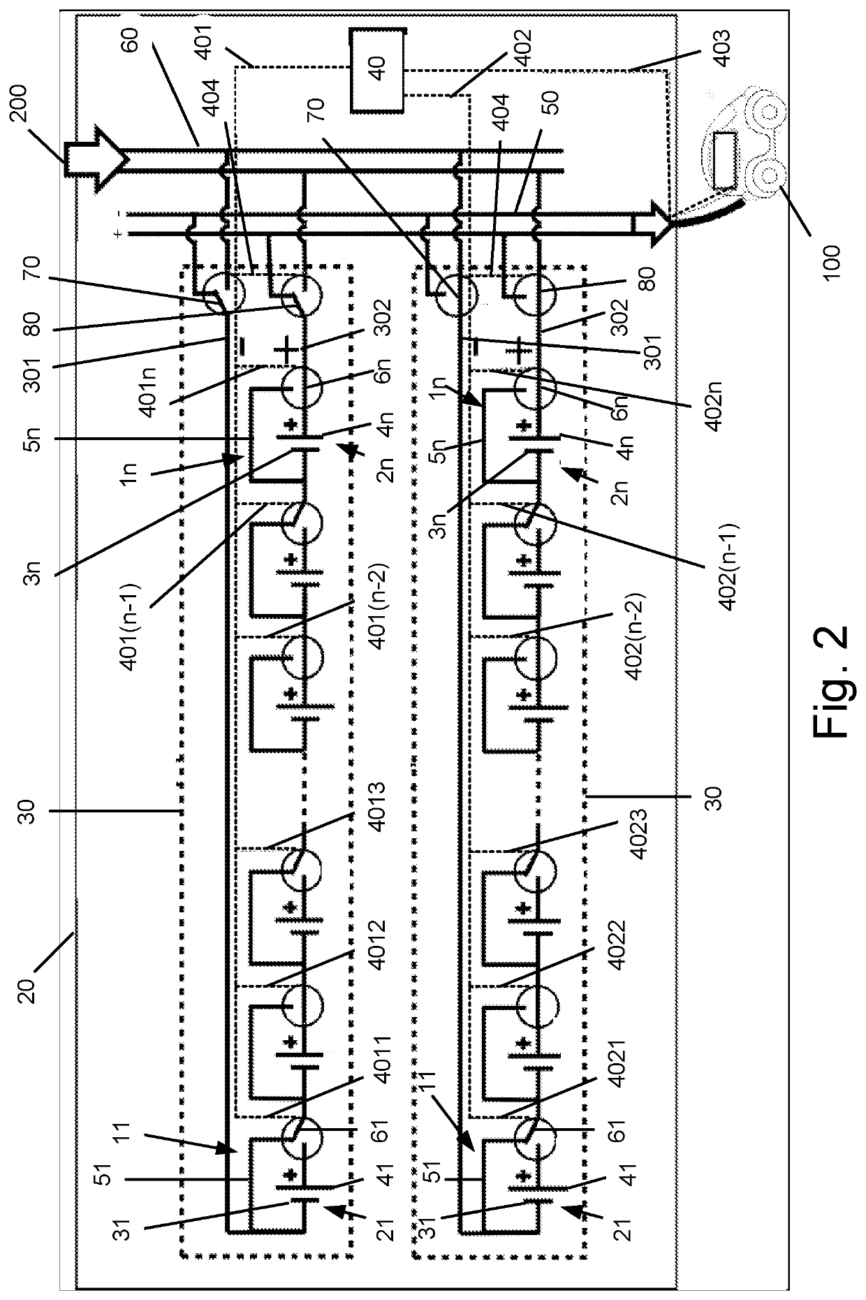
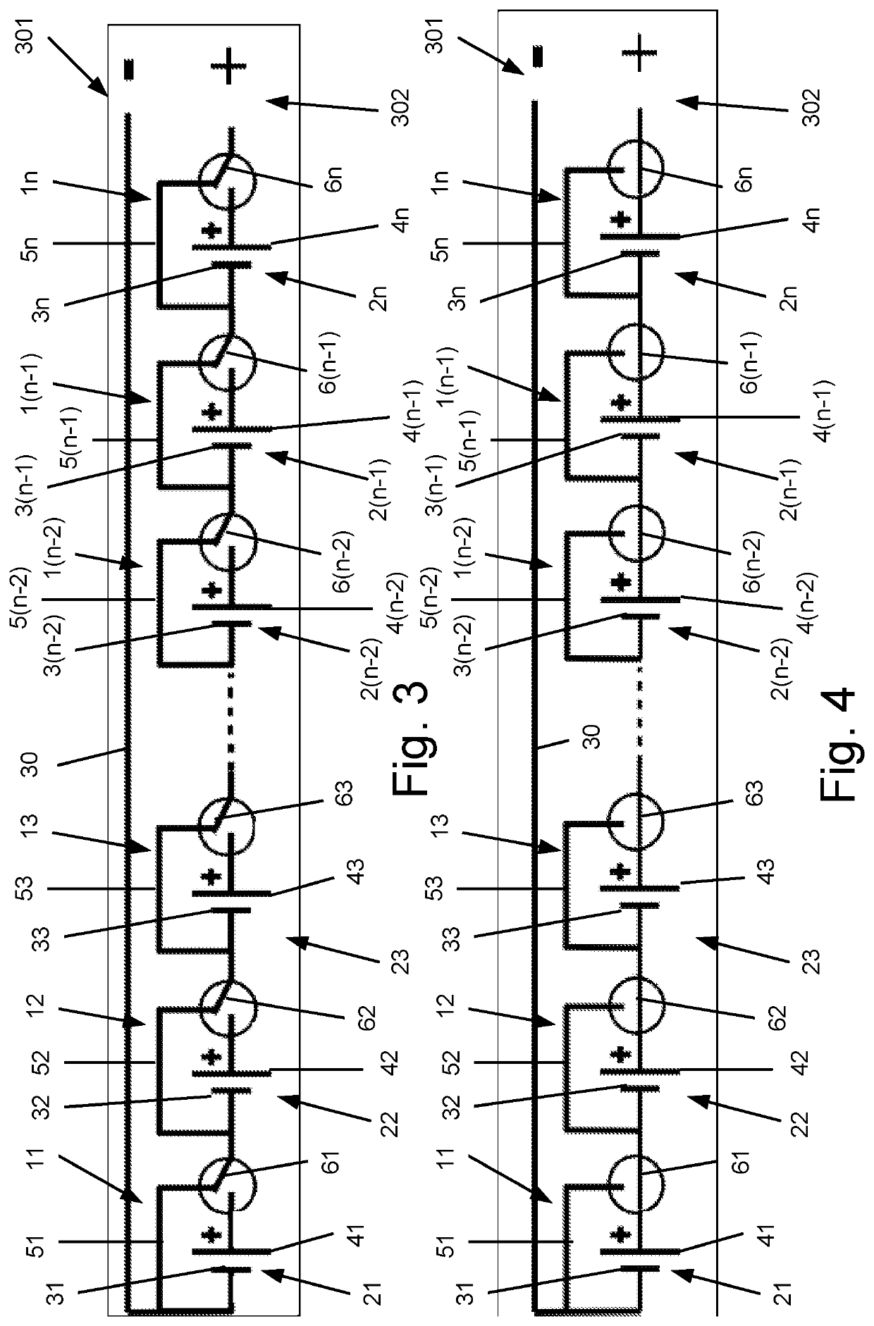
[0058]FIG. 1 illustrates a charging station 20 for charging electrical vehicles 100 according to the invention. The charging station 20 generally comprises a battery pack 30 with a plurality of n batteries 11, 12, 13, . . . 1(n−2), 1(n−1), 1n. The number n of batteries in a battery pack may be any number greater than or equal to 2. The batteries 11, 12, 13, . . . 1(n−2), 1(n−1), 1n are connected in series. The batteries 11, 12, 13, . . . 1(n−2), 1(n−1), 1n are all constructed in the same manner and will be described further below.
[0059]The battery pack 30 further comprises a first terminal 301 connected on one side to the negative terminal 31 of the battery cell 21 of the first battery 11 in the battery pack. The first terminal 301 thus forms a negative terminal of the battery pack. The first terminal 301 may on the other side be connected directly or indirectly to either an external source of electrical energy 200 or to an electrical vehicle 100 to be charged. A switch 70 is provid...
second embodiment
[0081]Turning finally to FIGS. 10 and 11, a battery 1′ of a battery pack 30 of a charging station 20 according to the invention is shown in the passive state and the active state, respectively. The battery 1′ differs from the battery 1 as shown in FIGS. 6 and 7 only in comprising a further switch 7 arranged in the battery inlet line 8, and thus between the negative terminal 3 of the battery cell 2 and the electrical circuit element 5.
[0082]The battery 1′ in other words comprise two switches 6 and 7, where the switch 6 is arranged in the battery outlet line 9, and thus between the positive terminal 4 of the battery cell 2 and the electrical circuit element 5, and where the switch 7 is arranged in the battery inlet line 8, and thus between the negative terminal 3 of the battery cell 2 and the electrical circuit element 5.
[0083]In charging stations 20 with battery packs 30 comprising batteries 1′ of the type shown in FIGS. 10 and 11, the control unit 40 is provided a connection line 40...
PUM
| Property | Measurement | Unit |
|---|---|---|
| electrical energy | aaaaa | aaaaa |
| electrical | aaaaa | aaaaa |
| power | aaaaa | aaaaa |
Abstract
Description
Claims
Application Information
 - R&D
- Intellectual Property
- Life Sciences
- Materials
- Tech Scout
- Unparalleled Data Quality
- Higher Quality Content
- 60% Fewer Hallucinations
Browse by: Latest US Patents, China's latest patents, Technical Efficacy Thesaurus, Application Domain, Technology Topic, Popular Technical Reports.
© 2025 PatSnap. All rights reserved.Legal|Privacy policy|Modern Slavery Act Transparency Statement|Sitemap|About US| Contact US: help@patsnap.com


