Eureka AIR delivers breakthrough ideas for toughest innovation challenges, trusted by R&D personnel around the world.

Placement of damage sensors in an air-temperature-managed equipment enclosure

Active Publication Date: 2020-04-23
NOKIA TECHNOLOGLES OY
View PDF0 Cites 1 Cited by
  • Summary
  • Abstract
  • Description
  • Claims
  • Application Information

AI Technical Summary

Benefits of technology

The patent text describes electrical equipment that has cooling fan(s) and damage sensors placed in a specific way to detect and mitigate damage caused by environmental factors. The placement of the damage sensors is designed to enhance their ability to detect damage with high sensitivity and certainty. This technology can improve the reliability and responsiveness of electrical equipment.

Problems solved by technology

Environmental conditions can have a drastic effect on the reliability and performance of electrical circuits, such as those used in the telecom equipment deployed in geographic regions characterized by harsh environments.
For example, the adverse effects of exposure to extreme temperatures, high humidity, atmospheric dust, and corrosive agents can cause some electrical circuits to fail.

Method used


Image

  • Placement of damage sensors in an air-temperature-managed equipment enclosure
  • Placement of damage sensors in an air-temperature-managed equipment enclosure
  • Placement of damage sensors in an air-temperature-managed equipment enclosure

Examples


Embodiment Construction

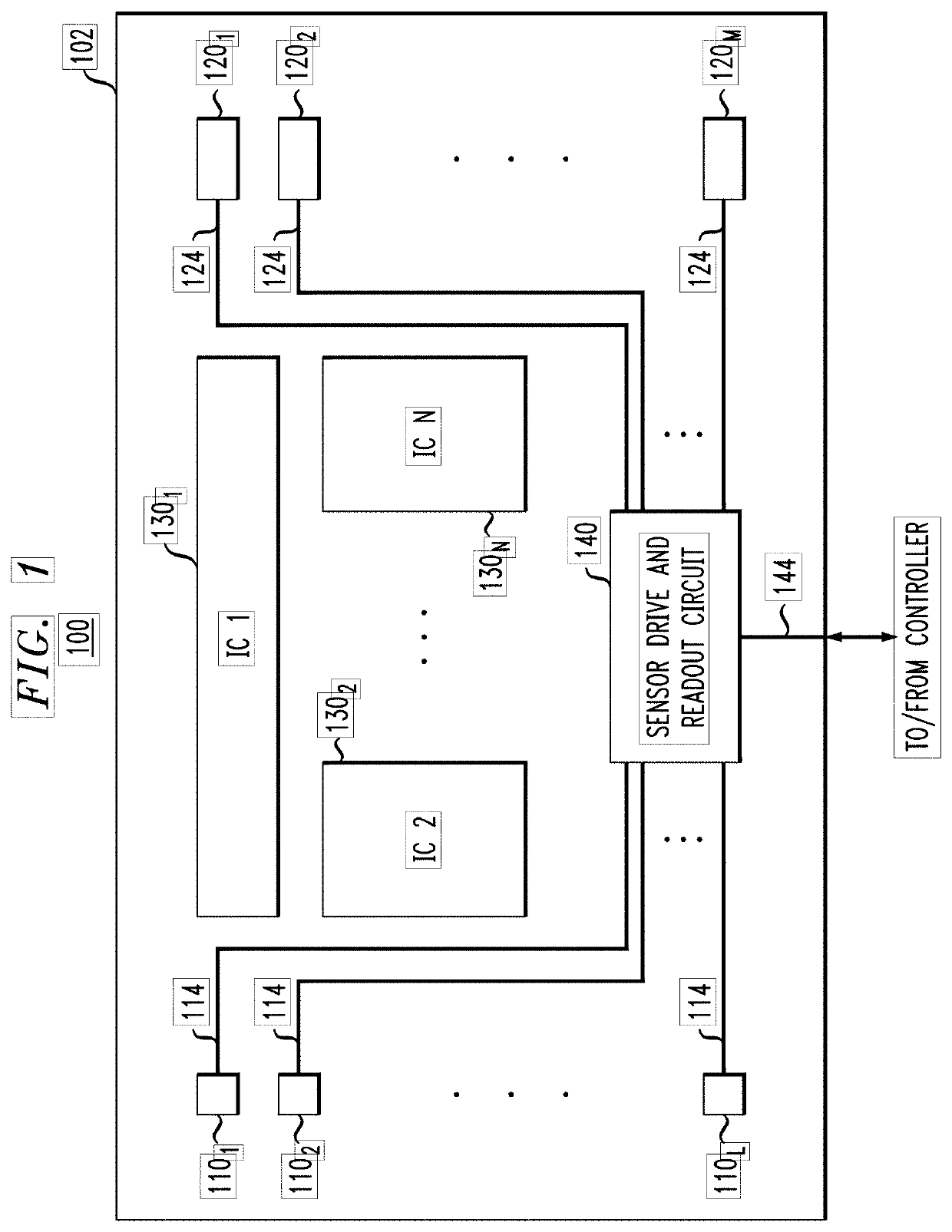
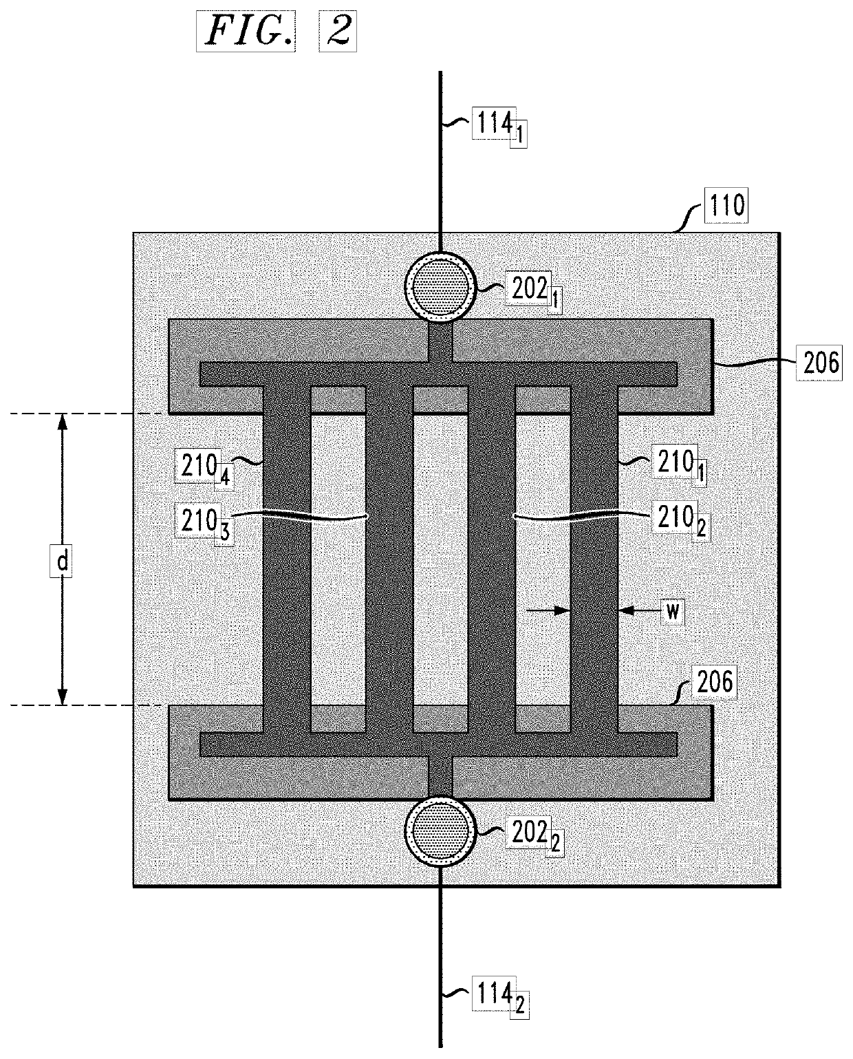
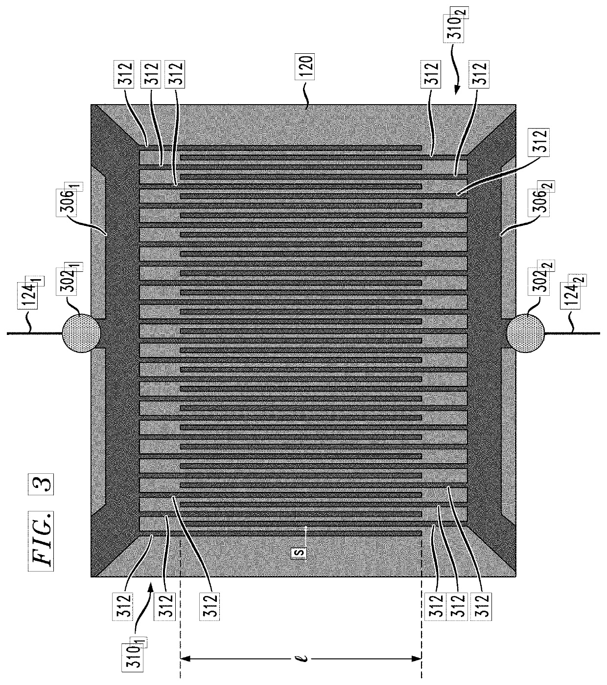
[0004]Disclosed herein are various embodiments of electrical equipment that may have: (i) cooling fan(s) to produce an airflow over electrical circuits by drawing air from the environment and (ii) damage sensors distributed in a non-uniform and / or targeted manner therein. In an example embodiment, one or more damage sensors may be placed within a narrow airflow zone, downstream from the cooling fans. In some embodiments, the placement of the damage sensor(s) may be characterized by one or more of the following: (i) the damage sensor(s) receive relatively high velocity airflow; (ii) the damage sensor(s) receive a turbulent portion of the airflow; and (iii) the damage sensor(s) receive a part of the airflow with a limited range of angles of impingement. Advantageously, such a placement of the damage sensor(s) can enhance the ability to detect environmentally induced equipment damage, e.g., with high sensitivity and / or certainty, as compared to said ability for the electrical equipment...


PUM


Abstract

A temperature-managed equipment enclosure, wherein the fans are configured to draw air from the environment, and wherein damage sensors are distributed in a non-uniform and / or targeted manner. In an example embodiment, most of the damage sensors may be placed within a relatively narrow zone downstream from the cooling fans. In some embodiments, a relatively large percentage of the damage sensors may be placed in the areas characterized by one or more of the following: (i) relatively high linear velocity of the airflow; (ii) turbulent airflow; and (iii) a certain range of angles of impingement of airflow on the equipment surfaces. Advantageously, the disclosed placement of damage sensors can be used to enhance the ability to detect environmentally induced equipment damage with high sensitivity and / or certainty.

Description

BACKGROUNDField[0001]The present disclosure relates to electrical equipment having sensors for estimating damage thereto.Description of the Related Art[0002]This section introduces aspects that may help facilitate a better understanding of the disclosure. Accordingly, the statements of this section are to be read in this light and are not to be understood as admissions about what is in the prior art or what is not in the prior art.[0003]Environmental conditions can have a drastic effect on the reliability and performance of electrical circuits, such as those used in the telecom equipment deployed in geographic regions characterized by harsh environments. For example, the adverse effects of exposure to extreme temperatures, high humidity, atmospheric dust, and corrosive agents can cause some electrical circuits to fail. It is therefore desirable to have a system in place that can estimate the working condition of environmentally exposed circuits and warn the equipment operator when a...

Claims


Application Information

Patent Timeline
IPC IPC(8): G01R31/28
CPCG01R31/2812G01R31/2836G01R31/2856G01N27/041G01N17/04
Inventor XU, CHEN
Owner NOKIA TECHNOLOGLES OY
Why Eureka
Eureka Blog
Learn More