Monitoring inmate movement with facial recognition

a technology of facial recognition and inmate movement, which is applied in the field of monitoring inmate movement with facial recognition, can solve the problems of inmates being hostile to wearing the transponder, rfid technology is problematic, and the office staff at secure facilities face many challenges in monitoring the whereabouts of inmates

Active Publication Date: 2020-04-23
CODEX CORPORATION
View PDF1 Cites 8 Cited by
  • Summary
  • Abstract
  • Description
  • Claims
  • Application Information

AI Technical Summary

Problems solved by technology

Officers at secure facilities face many challenges in monitoring the whereabouts of inmates.
The RFID technology is problematic in that it requires a transponder to be worn by the inmate.
Some inmates can be hostile to wearing the transponder.

Method used


Image

  • Monitoring inmate movement with facial recognition
  • Monitoring inmate movement with facial recognition
  • Monitoring inmate movement with facial recognition

Examples


example 1

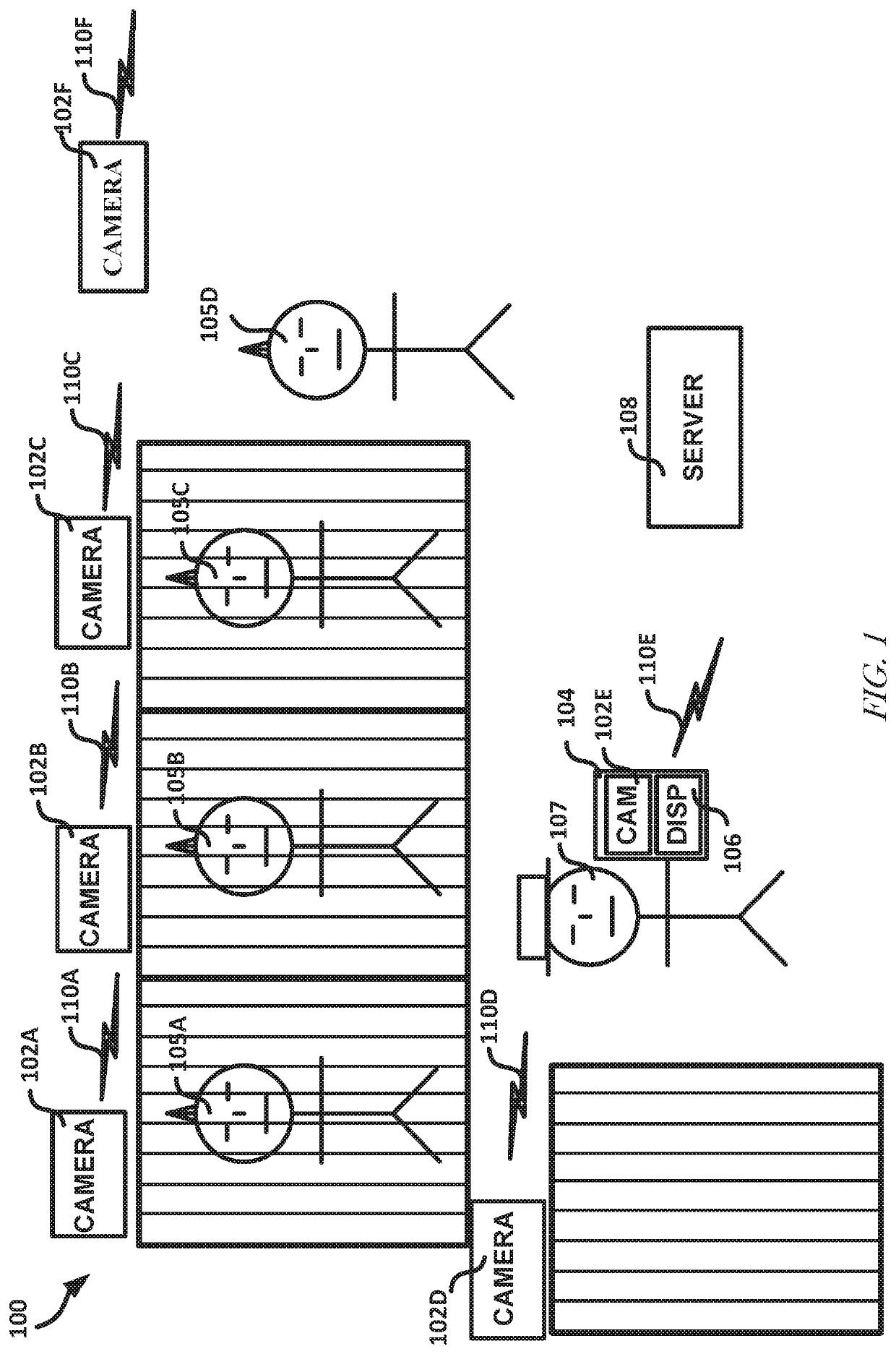
[0114 includes a system comprising cameras situated about a correctional facility to generate pixel data including first pixels corresponding to a face of a first offender in the correctional facility and an environment around the first offender corresponding to a location within the field of view of the camera, and a server configured to receive the pixel data from the cameras through a network connection, transmit the received data to a recognition service through the network, and receive an alert from the alert service that, based on facial recognition and location detection analysis performed on the pixel data by the recognition service, indicates a monitoring rule associated with the first offender is violated, an offender identification associated with the first offender, a location of the first offender in the correctional facility, and an indication of the monitoring rule violated.

[0115]In Example 2, Example 1 further includes, wherein the pixel data includes second pixels c...

example 20

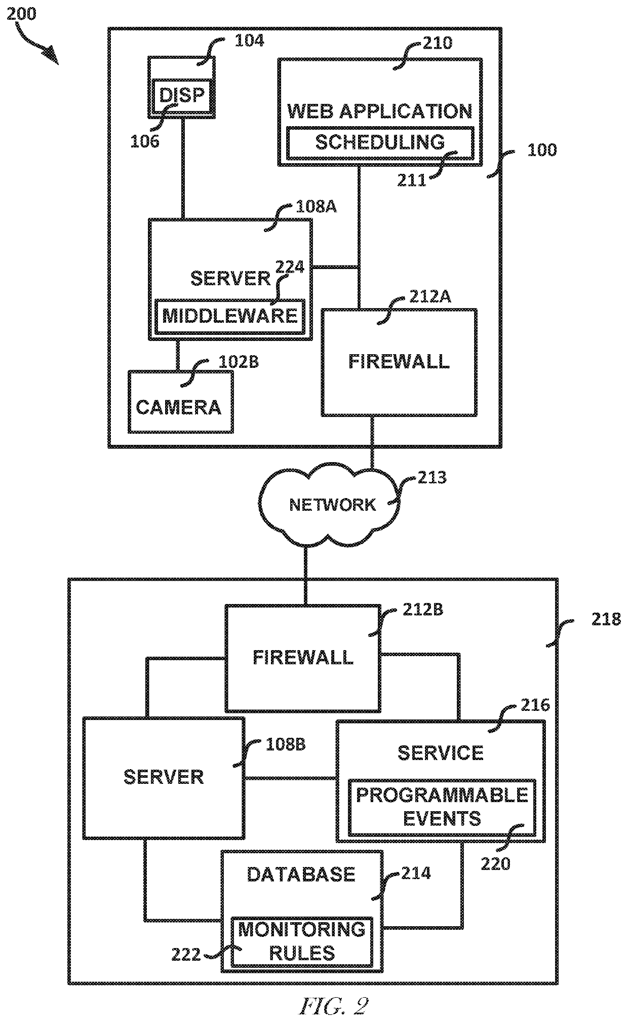
[0133 includes a system comprising a first network of a correctional facility to provide pixel data from cameras of the correctional facility, a second network including a database including a monitoring rule stored thereon that indicates a first offender at the correctional facility and a location or second offender that the first offender is restricted from in the correctional facility, and a server to receive the pixel data, and perform object recognition and / or facial recognition on the pixel data and identify the first offender and (1) the location of the first offender or (2) the second offender based on the pixel data and generate an alert to correctional facility personnel in response to detecting the monitoring rule is violated based on the identification.

[0134]In Example 21, Example 20 further includes, wherein the pixel data includes pixels corresponding to a distinct of the second offender and the monitoring rule includes data identifying the first offender and the secon...

example 29

[0142 includes a method of performing the operations of the system of at least one of Examples 20-28.

[0143]Example 30 includes a non-transitory machine-readable medium including instructions that, when executed by a machine, cause the machine to perform operations of the method of Example 29.


PUM


Abstract

The disclosure relates to systems and methods for automating offender documentation with facial or other recognition technique. A method can include generating, by cameras situated about a correctional facility, pixel data including first pixels corresponding to a face of a first offender in the correctional facility and an environment around the first offender corresponding to a location within the field of view of the camera, and providing, to a server, the pixel data from the cameras through a network connection, and receiving, from the server, an alert that, based on facial recognition and location detection analysis performed on the pixel data by the server, indicates a monitoring rule associated with the first offender is violated, an offender identification associated with the first offender, a location of the first offender in the correctional facility, and an indication of the monitoring rule violated.

Description

BACKGROUND INFORMATION[0001]Officers at secure facilities face many challenges in monitoring the whereabouts of inmates. Such monitoring can include visual inspection and verification on a strict schedule. Such monitoring can require the Officers to have a detailed knowledge of which inmates can associate with each other, and which areas of a premises the individual inmates are permitted to occupy.[0002]Prior solutions to monitoring the inmate movement includes using radio frequency identification (RFID) technology, sometimes in combination with radar. Through RFID transponder scans, last known whereabouts of an inmate can be determined. The radar can help indicate a direction an inmate is travelling, such as to help predict where the inmate is travelling.[0003]The RFID technology is problematic in that it requires a transponder to be worn by the inmate. Some inmates can be hostile to wearing the transponder. Some inmates can remove the transponder, thus making the RFD technology in...

Claims


Application Information

Patent Timeline
Patent Type & Authority Applications(United States)
IPC IPC(8): G06K9/00H04N5/247H04N7/18G06T7/73G06T7/292G08B21/22
CPCG06K9/00288G06T7/292G06K9/00778H04N5/247G06T2207/30242G06K9/00255G06T7/73H04N7/181G08B21/22G06T2207/30232H04N5/2226H04N7/188G08B13/19608G08B13/19673G08B13/19602G08B13/248G08B29/186G06V40/172G06V20/52H04N23/661H04N23/617G06V20/53G06V40/166H04N23/90
Inventor DALLEY, JR., KENNETH L.MONTEMORANO, FRANKSHAW, ANDREW
Owner CODEX CORPORATION
Why Eureka
Try Eureka